
Quick Start Manual

6
2. Verify the blower runs continuously. Check the air delivery
at the supply registers and adjust register openings for
balanced air distribution. If insufficient air is detected,
examine ductwork for leaks or obstructions.
3. Set the thermostat fan mode to AUTO and verify the
blower stops running.
System Cooling
1. Set the thermostat’s system mode to COOL and the
fan mode to AUTO. Gradually lower the thermostat
temperature setpoint below room temperature and
verifytheoutdoorunitandindoorblowerenergize.
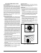
2. Verify blower wheel is spinning in direction indicated by
arrow. Feel the air being circulated by the indoor blower
and verify that it is cooler than ambient temperature.
Listen for any unusual noises. If unusual sounds occur,
determine the source of the noise and correct as
necessary.
3. Verify HI and LO refrigerant pressures.
4. Allow the system to operate for several minutes and then
set the temperature selector above room temperature.
Verify the fan and compressor cycle off with the
thermostat. NOTE: The blower should also stop unless
fan mode is set to the ON position.
System Heating (optional)
1. Set the thermostat's system mode to HEAT and the
temperature mode above room temperature.
2. Verify the optional heating equipment (furnace or
electricheat)andindoorblowerenergize.Feeltheair
being circulated by the indoor blower and verify that
it is warmer than ambient temperature. Listen for any
unusual noises. If unusual sounds occur, determine the
source of the noise and correct as necessary.
Refrigerant Charging
WARNING:
This split system air conditioner is shipped
charged with R410A refrigerant and ready
for installation. If repairs make it necessary
for evacuation and charging, it should only
be attempted by qualified trained personnel
thoroughly familiar with this equipment. Under
no circumstances should the owner attempt to
install and/or service this equipment. Failure to
comply with this warning could result in property
damage, personal injury, or death.
After refrigerant line connections are completed, it is
required that you leak check and evacuate the indoor
section and all line connections (using proper methods)
beforenalizingthefullsystemrefrigerantcharge.
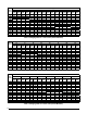
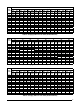
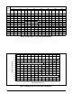
• Refrigerant charging charts are applicable only to
matched assemblies of NORDYNE equipment and
listed airflows for the indoor coil. Refer to Tables 3 - 9
(pages 8 & 9) and Figures 2 - 8 (pages 10 - 13) for
correct system charging.
• Outdoor units with non-AHRI listedindoor coils are
not recommended. Deviations from rated airflows or
non-listed combinations may require modification to the
expansion device and refrigerant charging procedures
for proper and efficient system operation.
• Therefrigerantchargecanbecheckedandadjusted
through the service ports provided external to the
outdoor unit. Use only gage line sets which have a
“Schrader” depression device present to actuate the
valve.
• Ahigh-pressureswitchisfactory-installedandlocated
in the liquid line internal to the outdoor unit. The switch
is designed to protect the system when very high
pressures occur during abnormal conditions. Under
normal conditions, the switch is closed. If the liquid
pressure rises above 575 psig, then the switch will
open and de-energize the outdoor unit. The switch
will close again once the liquid pressure decreases
to 460 psig. Please note that the switch interrupts the
thermostat inputs to the unit. Thus, when the switch
opens and then closes, there may be a 5 minute short
cyclingdelaybeforetheoutdoorunitwillenergize.
Charging the Unit in AC mode at outdoor temperatures
above55°Fforoptimizedsub-coolingof10°F-12°F.
1. With the system operating at steady-state, measure the
liquid refrigerant pressure (in psig) at the outdoor unit
service valve.
2. Measure the liquid refrigerant temperature (in
Fahrenheit) at the service valve.
3. Determine the required liquid refrigerant pressure from
the appropriate charging chart (Figures 2 - 8).
•IfthepressuremeasuredinStep1isgreaterthan
the required liquid refrigerant pressure determined in
Step 3, then there is too much charge in the system.
Remove refrigerant and repeat Steps 1 through 3
until the system is correctly charged.
•IfthepressuremeasuredinStep1islessthanthe
required liquid refrigerant pressure determined in
Step 3, there is too little charge in the system. Add
refrigerant and repeat Steps 1 through 3 until the
system is correctly charged.