
Installation Guide

5
• For venting system that extend through any zone above that on which the connected appliance is
located (except for one and two family dwellings), the vent system shall be enclosed with an enclosure
having a fire resistance rating equal to or greater than that of the floor or roof assemblies through
which it passes.
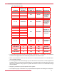
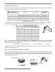
Clearances to Combustibles:
DIAMETER
CLEARANCE TO
COMBUSTIBLE
MATERIAL
MAXIMUM FLUE
GAS TEMP. (°F) ORIENTATION ENCLOSURE
4” - 24" 1"
26" - 32" 2"
4" - 32" Not Allowed 550 Horizontal
Fully enclosed
by combustible
material on
all sides
4" - 8" 1"
9" - 12" 2"
14" 3"
16" - 20" 4"
22" - 24" 5"
26" - 32" 6"
4” - 32" 0” 550 Any
Noncombustible
material
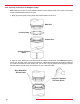
Enclosed on a
maximum of 2
sides (ceiling &
si de w a ll )
Horizontal550
550 Vertical
Fully enclosed
by combustible
material on
all sides
Gas: Special Gas Vent
Oil: Type L-Vent
4”- 8" CI Plus 3" 570 Any Enclosed
4”- 32" CI Plus &
ICI Plus
3" 570 Any Un-Enclosed
4"- 24" ICI Plus 3" 570 Any Enclosed
• The permitted clearances may differ by the appliance manufacturer. The appliance manufacturer’s
instructions and applicable local codes take precedence over this document.
• Do not place any type of insulation in any required clearance spaces surrounding the vent system.
• Design any enclosure to permit inspection of the system.
• Refer to the Definitions section of this document for important descriptions of combustible and
noncombustible material.