
Installation Guide

3
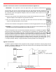
• Proper planning prior to installation is essential as to avoid possible contact with concealed plumbing or
electrical wiring inside walls, floors or ceilings as well as maintaining proper clearances. Be sure to plan
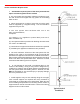
a sufficient number of supports for the entire system that will maintain the required straight-line pitch and
hold the system in place. A continuous straight-line pitch of at least 1/4 inch (2 degrees) to the foot on
horizontal runs must be maintained in order to properly rid the system of the corrosive condensate.
• The appliance manufacturer's instructions take precedence over this document.
• Failure to conform to any of these requirements may violate local, state, national or international codes
as well as create conditions which may cause catastrophic property damage or personal injury. Failure to
conform to any of these requirements will also void any warranties, stated or implied.
• Saf-T Vent SC vent sections, or other Saf-T Vent products, must be used throughout the entire length
of the system. Alternatives such as galvanized pipe, PVC, nonmetallic pipe, prefabricated chimney, field-
fabricated vents or Type B vent sections must not be used. Do not mix pipes, fittings, or joining methods
from different manufacturers.
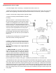
• If called for by the appliance manufacturer’s instructions, a drain fitting must be located as close as
possible to the appliance flue outlet.
• More than one appliance may not be interconnected to any part of the venting system. All connected
appliances must be all natural draft or all forced draft.
• Any penetrations of ceilings, floors, or walls must be properly fire-stopped.
• Whenever gas-burning equipment is installed in the same space where halogenated substances may
exist (refrigerants, solvents, bleaches, salts, etc.), clean outside air must be utilized for combustion.
• The vent system shall not be routed into, through or within any other actively used vent or chimney.
• Seal weather exposed joints of the outer jacket with foil tape or an exterior grade silicone sealant.
General Installation Requirements:
Pre-Installation Considerations:
Introduction:
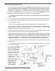
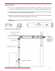
Saf-T Vent SC is an advanced concentric vent system designed for zero clearance installation in residential
and light commercial applications. The inner wall is constructed from superferritic AL 29-4C
®
stainless steel.
The outer wall is also constructed from stainless steel, providing durability and a lasting finish.
The double-wall construction of Saf-T Vent SC allows the system to be fully enclosed by combustible materials
at zero or 1-inch clearance depending on orientation and flue gas temperature. Saf-T Vent SC is UL and CUL
Listed to UL 1738 (File MH16161). It may be used on negative, neutral, and positive pressure systems up to
8 inches w.c.
As a Special Gas Vent system: Saf-T Vent is approved for use on ANSI Category I, II, III, and IV Gas-Burning
Appliances and certain Direct Vent appliances. Saf-T Vent SC is appropriate for use on appliances that
specify an AL 29-4C venting system.
As a Sealed Combustion system: The unique concentric design of Saf-T Vent SC also allows it to function
as a pipe-in-a-pipe vent. Products of combustion are exhausted out through the inner wall while combustion
air is drawn in through the outer wall. An appliance can be direct-vented with only a single penetration through
the building structure. This application must be approved by the Appliance Manufacturer
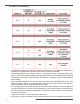
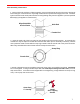
Note: Saf-T Vent SC includes an integral seal and does not require RTV sealant. However, sealant may be
necessary when connecting Saf-T Vent SC components directly to certain appliance flue collars and to the
gasket-less Saf-T Vent GC and Saf-T Vent CI vent systems.
For applications up to 550°F/288°C, approved sealants include GE RTV 106 and Dow Corning 736.
For applications up to 300°F/149°C, approved sealants include GE RTV 106 and Dow Corning 732.