Owner’s Manual Installation and Operation Model(s): CERONA-36 CERONA-42 CAUTION DO NOT DISCARD THIS MANUAL • Important operating and maintenance instructions included. • Read, understand and follow these instructions for safe installation and operation. WARNING: If the information in these instructions is not followed exactly, a fire or explosion may result causing property damage, personal injury, or death.
Read this manual before installing or operating this appliance. Please retain this owner’s manual for future reference. Congratulations Congratulations on selecting a Heat & Glo gas appliance —an elegant and clean alternative to wood burning appliances. The Heat & Glo gas appliance you have selected is designed to provide the utmost in safety, reliability, and efficiency. This Owner’s Manual should be retained for future reference.
Table of Contents 9 Gas Information 1 Listing and Code Approvals A. B. C. D. E. F. G. Appliance Certification . . . . . . . . . . . . . . . . . . . . . . . . . . . . BTU Specifications . . . . . . . . . . . . . . . . . . . . . . . . . . . . . . . High Altitude Installations . . . . . . . . . . . . . . . . . . . . . . . . . . Non-Combustible Materials Specification. . . . . . . . . . . . . . Combustible Materials Specification . . . . . . . . . . . . . . . . . Electrical Codes . . . . . . . . . . . . . . .
1 Listing and Code Approvals A. Appliance Certification C. High Altitude Installations U.L. Listed gas appliances are tested and approved without requiring changes for elevations from 0 to 2000 feet in the U.S.A. and Canada. MODELS: CERONA-36, CERONA-42 LABORATORY: Underwriters Laboratories, Inc. (UL) TYPE: Direct Vent Gas Appliance Heater STANDARD: ANSI Z21.88b-2005 • CSA2.
Note: The following requirements reference various Massachusetts and national codes not contained in this document. G.
2 Getting Started A. Design and Installation Considerations C. Inspect Appliance and Components Heat & Glo direct vent gas appliances are designed to operate with all combustion air siphoned from outside of the building and all exhaust gases expelled to the outside. No additional outside air source is required. WARNING Inspect appliance and components for damage. Damaged parts may impair safe operation. • Do NOT install damaged components. • Do NOT install incomplete components.
D. Inspect Firebox Surface cracking or crazing of firebrick material is normal and expected. The following types of cracks are acceptable and do not require replacement of the unit or the firebox: • Cracks that do not propagate entirely thru the material. • Light fracture lines or “spider-webbing” on the surface of the material. • Cracks that are less than 1/32 in. wide and less than 3 in. long. • If cosmetically unacceptable, such cracks may be repaired with the SRV-PACK service kit.
3 Framing and Clearances WARNING Note: • Illustrations reflect typical installations and are FOR DESIGN PURPOSES ONLY. • Illustrations/diagrams are not drawn to scale. • Actual installation may vary due to individual design preference. Fire Risk Provide adequate clearance: • Around air openings • To combustibles • For service access Locate appliance away from traffic areas. A.
insulation. If the appliance is being installed on a cement slab, a layer of plywood may be placed underneath to prevent conducting cold up into the room. B. Constructing the Appliance Chase A chase is a vertical boxlike structure built to enclose the gas appliance and/or its vent system. Vertical vents that run on the outside of a building may be, but are not required to be, installed inside a chase. C. Clearances Construction of the chase may vary with the type of building.
D. Mantel Projections CEILING COMBUSTIBLE SHEATHING CLEARANCE TO CEILING 1 in.
E. Hearth Extension WARNING 8 in. min. (203 mm) Fire Risk. Hearth extension required to protect combustible floors in front of appliance. 1 in. max. (25 mm) • An 8 inch minimum hearth extension must be constructed of non-combustible material. COMBUSTIBLE SURFACE MARBLE, GRANITE, TILE OR OTHER NON-COMBUSTIBLE HEARTH EXTENSION BOTTOM OF FIREPLACE Figure 3.7 Fireplace sitting on combustible surface. SURFACE MAY BE COMBUSTIBLE 1 INCH MAX.
4 Termination Locations A. Vent Termination Minimum Clearances HORIZONTAL OVERHANG 2 FT. MIN. WARNING 20 INCHES MIN. VERTICAL WALL LOWEST DISCHARGE OPENING Fire Risk. Explosion Risk. Inspect external vent cap regularly. • Ensure no debris blocks cap. • Combustible materials blocking cap may ignite. • Restricted air flow affects burner operation. GAS DIRECT VENT TERMINATION CAP X 12 ROOF PITCH IS X/ 12 H (MIN.) - MINIMUM HEIGHT FROM ROOF TO LOWEST DISCHARGE OPENING Roof Pitch H (Min.) Ft.
M N P R Q (See Note 2) V T V S Electrical Service S V D* V V = VENT TERMINAL A B D* X = AIR SUPPLY INLET = 12 inches.................clearances above grade, veranda, (See Note 1) porch, deck or balcony = 12 inches.................clearances to window or door that may be opened, or to permanently closed window. (Glass) = 18 inches.................vertical clearance to unventilated soffit or to ventilated soffit located above the terminal *30 inches................
B. Continue Adding Vent Components CORRECT COMBUSTIBLE SURFACE DIRECTION UP WARNING Fire Risk. Installation of this appliance may require the use of heat shield 385-290 above the first 900 elbow in the venting system. To Install the Heat Shield: HEAT SHIELD 90º ELBOW Figure 4.6 1. Determine if the heat shield is required. Do so by measuring the vertical distance between the top horizontal surface of the elbow to any combustible surface above.
5 Vent Information and Diagrams A. Vent Table Key The abbreviations listed in this vent table key are used in the vent diagrams. First section (closest to appliance) of vertical length V2 Second section of vertical length H1 First section (closest to appliance) of horizontal length H2 Second section of horizontal length Vertical 12 V1 8-1/2 in. WARNING Fire Hazard. Explosion Risk. Asphyxiation Risk.
D. Vent Diagrams WARNING Fire Risk. Explosion Risk. Do NOT pack insulation or other combustibles between ceiling firestops. • ALWAYS maintain specified clearances around venting and firestop systems. • Install wall shield and ceiling firestops as specified. Failure to keep insulation or other material away from vent pipe may cause fire. 1. Top Vent - Horizontal Termination V1 Minimum One Elbow Cerona-36 ONLY V1 H1 1/2 ft 1 ft 2 ft 3 ft 4 ft 5 ft 6 ft 7 ft 8 ft 152 mm 305 mm 610 mm 914 mm 1.2 m 1.
1. Top Vent - Horizontal Termination - (continued) V1 Minimum Three Elbows Cerona-36 ONLY H2 V2 1/2 ft 1 ft 2 ft 3 ft 4 ft 5 ft 6 ft 7 ft 152 mm 305 mm 610 mm 914 mm 1.2 m 1.5 m 1.8 m 2.1 m H1 Maximum 3 ft 4 ft 7 ft 10 ft 13 16 17 22 914 mm 1.2 m 2.1 m 3.0 m 4.0 m 4.9 m 5.2 m 6.7 m H1 + H2 = 22 ft. (6.7 m) Max. V1+ V2 + H1 + H2 = 62 ft. (18.9 m) Max. V1 H1 Note: Must have Minimal Vertical Vent a minimum vertiModel ft. mm cal vent before 1/2 152 attaching a 90º Cerona-36 elbow to the unit.
2. Top Vent - Horizontal Termination - (continued) V1 Minimum Two Elbows Cerona-36 ONLY V2 1/2 ft 1 ft 2 ft 3 ft 4 ft 5 ft 6 ft 7 ft 8 ft 152 mm 305 mm 610 mm 914 mm 1.2 m 1.5 m 1.8 m 2.1 m 2.4 m H1 Maximum 2 ft 2 ft 5 ft 8 ft 11 ft 14 ft 17 ft 20 ft 23 ft 610 mm 610 mm 1.5 m 2.4 m 3.4 m 4.3 m 5.2 m 6.1 m 7.0 m H1 = 23 ft. (7.0 m) Maximum V1 + V2+ H1 = 63 ft. (19.2 m) Maximum V1 H1 Note: Must have Minimal Vertical Vent a minimum vertiModel ft.
6 Vent Clearances and Framing A. Pipe Clearances to Combustibles B. Wall Penetration Framing Combustible Wall Penetration WARNING Fire Risk. Explosion Risk. Maintain vent clearance to combustibles as specified. • Do not pack air space with insulation or other materials. Failure to keep insulation or other materials away from vent pipe may cause fire. 3 in. TOP CLEARANCE Frame a hole in a combustible wall for an interior wall shield firestop, (Figure 6.3) whenever a wall is penetrated.
C. Vertical Penetration Framing WARNING Fire Hazard Keep loose materials or blown insulation from touching the vent pipe. • National building codes recommend using attic shield to keep loose materials/ blown insulation from contacting vent. • Hearth & Home Technologies requires the use of an attic shield. ATTIC ABOVE 10 IN. (254 MM) Installing the Ceiling Firestop • Frame an opening 10 inches by 10 inches whenever the vent system penetrates a ceiling/floor (see Figure 6.4).
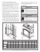
7 Appliance Preparation A. Removing Non-combustible Facing Material Assembly CAUTION The non-combustible assembly is located on the back of appliance (see Figure 7.1). Handle with care. • Non-combustible material may be damaged if dropped. • Hold non-combustible pieces in place. • Remove and save two screws from upper brackets (see Figure 7.1). • Remove non-combustible pieces. • Remove and save three screws from lower bracket (see Figure 7.1). • Discard brackets.
B. Securing and Leveling the Appliance CAUTION Sharp Edges • Wear protective gloves and safety glasses during installation. WARNING Fire Risk. • ALWAYS maintain specified clearances around the appliance. • Do NOT notch into the framing around the appliance spacers. Failure to keep insulation, framing or other material away from the appliance may cause fire. WARNING Fire Risk. • Prevent contact with sagging, loose insulation.
• Attach the left and right side pieces to the framing members. (See Figure 7.3). NON-COMBUSTIBLE FACING MATERIAL D. Installing Flue Restrictors Locate the flue restrictor and two screws inside the manual bag. Use the following table to determine which restrictors to use for the vent run. Vent Run Vertical 15 ft. - 50 ft. Cerona-36 1-1/4 Cerona-42 1-1/4 Mount the flue restrictor to the flapper door using two screws (see Figure 7.5). EXHAUST COLLAR FLUE RESTRICTOR FIREBOX B 1 in.
8 Installing Vent Pipe A. Assembly of Vent Sections WARNING WARNING Fire Risk Explosion Risk If slip section seals are broken during the removal of the termination cap, gas will leak and a fire or explosion may occur. Do not break silicone seals on slip sections. Do not mix pipe, fittings or joining methods from different manufacturers. WARNING Fire Risk Exhaust Fumes Risk Impaired Performance of Appliance • Overlap pipe slip sections at least 1-1/2 inches. • Use pilot holes for screws.
Note: Make sure that the seams are not aligned to prevent Assembling DVP-12A Slip Sections The outer flue of the slip section should slide over the outer flue of the pipe section and into (inner flue) the last pipe section (see Figure 8.7) . unintentional disconnection. Slide together to the desired length, making sure that a 1-1/2 inch outer flue overlap is maintained between the pipe section and slip section.
B. Securing the Vent Sections C. Disassembly of Vent Sections Vertical Sections To disassemble any two pieces of pipe, rotate either section (see Figure 8.11), so that the seams on both pipe sections are aligned (see Figure 8.12). They can then be carefully pulled apart. Vertical sections of pipe must be supported every 8 feet after the 25 foot maximum unsupported rise. The vent support or plumber’s strap (spaced 120° apart) may be used to do this (see Figure 8.9).
D. Installing Heat Shield and Horizontal Termination Cap WARNING Fire Hazard Impaired performance of appliance • Telescoping flue section of termination cap MUST be used when connecting pipe section to termination cap. • Maintain a 1-1/2 inch minimum overlap on telescoping flue section of termination cap. Installing the Horizontal Termination Cap Vent termination must not be recessed in the wall. Siding may be brought to the edge of the cap base.
E. Installing Roof Flashing and Vertical Termination Cap To install roof flashing see Figure 8.16. For installation of vertical termination cap see minimum vent heights for various pitched roofs (see Figure 8.14). HORIZONTAL OVERHANG 2 FT. MIN. 20 INCHES MIN. VERTICAL WALL Caulk the gap between the roof flashing and the outside diameter of the pipe. Also caulk the perimeter of flashing that contacts roof surface as shown in Figure 8.16.
Assembling and Installing Storm Collar CAUTION Sharp Edges • Wear protective gloves and safety glasses during installation. Connect both halves of the storm collar with two screws (see Figure 8.17). Wrap the storm collar around the exposed pipe section and align brackets. Insert a bolt (provided) through the brackets and tighten nut to complete storm collar assembly (see Figure 8.18). Slide the assembled storm collar down the pipe section until it rests on the roof flashing. Figure 8.
9 Gas Information A. Fuel Conversions C. Gas Connection Before making gas connections ensure that appliance being installed is compatible with the available gas type. Any natural or propane gas conversions necessary to meet the appliance and locality needs must be made by a qualified technician using Hearth & Home Technologies specified and approved parts. Note: Have the gas supply line installed in accordance with local building codes, if any. If not, follow ANSI 223.1.
• Ensure that gas line does not come in contact with outer wrap of appliance. Follow local codes. • Incoming gas line should be piped into the valve compartment and connected to the 1/2 inch connection on the manual shutoff valve. WARNING Fire or Explosion Hazard • • • • Gas buildup during line purge may ignite. Purge should be performed by qualified technician. Ensure adequate ventilation. Ensure there are no ignition sources such as sparks or open flames. HIGH ALTITUDE INSTALLATIONS U.L.
10 Electrical Information A. Recommendation for Wire C. Intellifire Ignition System Wiring This appliance requires 110-120 VAC be wired to the junction box for proper operation of the appliance. This appliance uses an Intellifire ignition system. This appliance requires a 110 VAC supply to the appliance junction box for operation. A wiring diagram is shown in Figure 10.1.
For units WITHOUT factory installed Rocker Switch BLACK BATTERIES SWITCH AND WIRE ASSEMBLY SUPPLIED WITH WSK-MLT WHITE BROWN BLACK GREEN YELLOW or WHITE RED ORANGE RED BLACK IPI MODULE G W* R BROWN BROWN RED BLACK RED (MALE/FEMALE) 3V DC RED (FEMALE/MALE) FLAME SOLENOID 1 2 3 4 5 6 7 8 GREEN R W* G IPI VALVE RED REAR VIEW GROUND BLACK FRONT VIEW RED FLAME ON RED ORANGE ORANGE FLAME HIGH/LOW AC PLUG ADAPTER WIRES AUX CONNECTION YELLOW BLACK FAN THERMOSTAT BLACK GROUND PIGTAIL GR
Note TO APPLIANCE INSTALLERS: To protect appliance after installation, but before use, please replace corrugated splatterguard on unit per directions noted below. STEP 3 Push in folded bottom tab over control module heat shield, placing lower outside notches on glass support brackets. See Figure 3 and 4. STEP 1 For Cerona-36, center left to right over glass and fold top center section under top heat shield as in figure 1.
11 Finishing A. Mantel Projections Figure 11.1 shows the minimum vertical and corresponding maximum horizontal dimensions of appliance mantels or other combustible projections above the top front edge of the appliance. INTERIOR WALL TOP VIEW MANTEL LEG OR WALL PROJECTIONS CEILING 1 in. TYPICAL A COMBUSTIBLE FACING MATERIAL A 12" 11" 10" 9" FIREPLACE HEADER 8" E 7" MINIMUM FROM TOP OF ARCH OPENING TO CEILING 6" 5" 4" 3" If A minimum is _____, then B maximum is ______.
B. Facing Material WARNING Fire Risk. Do NOT obstruct air inlet or outlet grilles. Do NOT modify grilles. • Modifying or covering grilles could cause temperature rise and fire hazard. Finishing materials must not interfere with: • Air flow through grilles or louvers. • Operation of louvers or doors. • Access for service. COMBUSTIBLE SHEATHING CLEARANCE TO CEILING CEILING B MINIMUM A NON-COMBUSTIBLE FACING MATERIAL IN SHADED AREAS WARNING Fire Risk.
C. Finishing Material Options Finishing Material Thickness greater than 1-1/4 inch Finishing Material Thickness from 3/4 in. to 1-1/4 in. A steel template (Cerona-36 Template or Cerona-42 Template) is available for purchase to use instead of constructing a template. Finishing material within this thickness range can be brought to 1/2 inch behind the door top and sides. These non-combustible finishing materials must never overlap or obstruct the air outlet/inlet grille areas.
NON-COMBUSTIBLE BOARD FACING TEMPLATE Figure 11.7 Position of board and template NAILING TABS (BOTH SIDES) NO HE N-C AR OM TH BU EX ST TE IBL NS E IO N D. Hearth Extension WARNING A Fire Risk. B Hearth extension required to protect combustible floors in front of appliance. • An 8 inch minimum hearth extension must be constructed of non-combustible material. Cerona-36 The base of the fireplace may sit on a combustible surface.
12 Appliance Setup A. Remove Shipping Materials D. Ember Placement Remove shipping materials from inside or underneath the firebox. B. Clean the Appliance Clean/vacuum any sawdust that may have accumulated inside the firebox or underneath in the control cavity. C. Accessories Install approved accessories per instructions included with accessories. See Service Parts List for appropriate accessories. Refer to Section 16. HEAT-ZONE/HEAT-DUCT KNOCKOUT WARNING Explosion Risk.
E. Positioning the Logs Log Assembly: LOGS-Cerona36 Model: Cerona-36 If the gas logs have been factory installed they should not need to be positioned. If the logs have been packaged separately, refer to the following instructions. 5 6 1 3 4 2 Figure 12.3 CAUTION: Carefully remove the logs from the packaging. Logs are fragile! 1 1 B Figure 12.4 A Figure 12.5 STEP 1.
4 5 Figure 12.8 Figure 12.9 STEP 4. STEP 5. LOG #4 (SRV2106-704): Log #4 is form fitted to the burner. It sits on the middle portion of the burner as shown. LOG #5 (SRV2106-702): Place the right portion of log #5 on the formed area of log #1. Place the left side on the grate. Set the notch of the log on the grate. A 6 Figure 12.10 STEP 6. LOG #6 (SRV2106-706): Rest bottom notch of log #6 on the grate tine and the top part on formed section of log #5 (A).
Log Assembly: LOGS-Cerona42 Model: Cerona-42 If the gas logs have been factory installed they should not need to be positioned. If the logs have been packaged separately, refer to the following instructions. 1 5 CAUTION: Carefully remove the logs from the packaging. Logs are fragile! 4 6 2 3 Figure 12.12 STEP 1. LOG #1 (SRV2107-701): Place log #1 over the back side of the burner plate and slide forward until log hits the grate. Log cut out should fit over pilot bracket. See Figure 12.13.
STEP 3. LOG #3 (SRV2107-703): Place the notch on the tip of log #3 over the locating tab on log #1. Place the left leg of the log on the far left grate tine (A). See Figure 12.15. TAB A 3 Figure 12.15 STEP 4. LOG #4 (SRV2107-704): Place the left formed end of log #4 on the burner detail located under log #3, and the notch on the right end of log #4 on the front grate bar. Log #3 may need to be adjusted for proper placement. See Figure 12.
STEP 7. LOG #6 (SRV2107-706): Place notch of log #6 over the left grate tine. Log should rest on the flat of log #5 and the flat on log #3. You may need to reposition log #5 to get log #6 to sit in the flats. See Figure 12.18. 6 Figure 12.18 F. Glass Assembly WARNING Handle glass doors with care. • Inspect the gasket to ensure it is undamaged. • Inspect the glass for cracks, chips or scratches. • Do NOT strike, slam or scratch glass.
13 Operating Instructions A. Before Lighting Appliance This appliance has an Intellifire ignition system. CAUTION WARNING HOT SURFACES! Glass and other surfaces are hot during operation AND cool down. If installing Intellifire ignition battery backup: • Do not install batteries if the backup mode may not be used for extended time. • Batteries may leak. • Install batteries only when needed for power outage. Hot glass will cause burns.
B. Lighting Appliance IPI Ignition FOR YOUR SAFETY READ BEFORE LIGHTING WARNING: If you do not follow these instructions exactly, a fire or explosion may result causing property damage, personal injury or loss of life. A. This appliance is equipped with an intermittent pilot ignition (IPI) device which automatically lights the burner. Do not try to light the burner by hand. • Immediately call your gas supplier from a neighbor’s phone. Follow the gas supplier’s instructions. B.
C. After Appliance is Lit CAUTION Initial Break-in Procedure When you light the appliance, you may notice that it produces heat which does have an associated odor or smell. If you feel this odor is excessive it may require the initial three to four hour continuous burn on high followed by a second burn up to 12 hours to fully drive off any odor from paint and lubricants used in the manufacturing process. Condensation of the glass is normal.
14 Troubleshooting With proper installation, operation, and maintenance your gas appliance will provide years of trouble-free service. If you do experience a problem, this troubleshooting guide will assist a qualified service person in the diagnosis of a problem and the corrective action to be taken. This troubleshooting guide can only be used by a qualified service technician. A. Intellifire Ignition System Sympton 1. The ignitor/module makes noise, but no spark. 2.
Intellifire Ignition System - (continued) Symptom 3. (Continued) Pilot lights but continues to spark, and main burner will not ignite. (If the pilot continues to spark after the pilot flame has been lit, flame rectification has not occurred.) 4. Pilot sparks, but Pilot will not light. Possible Cause Corrective Action c. Module is not grounded. Verify that module is securely grounded to metal chassis of appliance. Verify that wire harness is firmly connected to module. d.
15 Maintaining and Servicing Appliance A. Maintenance Tasks Although the frequency of appliance servicing and maintenance will depend on use and the type of installation, a qualified service technician should perform an appliance checkup at the beginning of each heating season. WARNING Risk of injury or property damage. Before servicing: • Turn off gas. • Turn off electricity to appliance. • Disable remote control, if one is present. • Ensure appliance is completely cooled.
Inspect Doors, Surrounds and Fronts Maintenance Tasks 1. Assess condition of screen and replace as necessary. Recommend addition of screen if one is not present. 2. Inspect for scratches, dents or other damage and repair as necessary. 3. Verify no obstructions to airflow through the louvers. 4. Verify maintenance of proper clearance to combustible household objects. Gasket Seal, Glass Assembly and Glass 1. Inspect gasket seal and its condition. 2.
16 Reference Materials A. Appliance Dimension Diagram Dimensions are actual appliance dimensions. Use for reference only. For framing dimensions and clearances refer to Section 3.
B. Vent Components Diagrams Pipe Effective Height/Length DVP4 DVP Pipe (see chart) 10-1/2 in. (267 mm) Effective Length Inches Millimeters 4 102 DVP6 6 152 DVP12 12 305 DVP24 24 610 DVP36 36 914 DVP48 48 1219 DVP6A 3 to 6 76 to 152 DVP12A 45 ° 4-7/8 in. ( 276 mm) 10-7/8 in. (276 mm) ° DVP45 (45 Elbow) 3 to 12 76 to 305 DVP12MI 3 to 12 76 to 305 DVP24MI 3 to 24 76 to 610 11-3/8 in. (289 mm) 10 in. (254 mm) 10 in. (254 mm) 1 in. (25 mm) 7-3/8 in. (187 mm) 24 in.
B. Vent Components Diagrams (continued) Note: Heat shields MUST overlap by a minimum of 1-1/2 in. (38 mm). The heat shield is designed to be used on a wall 4 in. to 7-1/4 in. (102 mm to 184 mm) thick. If wall thickness is less than 4 in. (102 mm) the existing heat shields must be field trimmed. If wall thickness is greater than 7-1/4 in. (184 mm) a DVP-HSM-B will be required. 8 in. (203 mm) Heat Shield 15-1/8 in. (384 mm) Term Cap Max Effective Length 12 in.
B. Vent Components Diagrams (continued) 31 in. (787 mm) 13-1/4 in. (367 mm) 24-5/8 in. (625 mm) 27-1/2 in. (127 mm) 24-5/8 in. (625 mm) 13-1/4 in. (367 mm) RF6M Roof Flashing Multi-pak RF12M Roof Flashing Multi-pak 5 in. (127 mm) 13-3/4 in. (349 mm) 11-7/8 in. (302 mm) 5 in. (127 mm) 13-7/8 in. (352 mm) 13-3/4 in. (349 mm) DVP-BEK2 DVP-HPC Cap Brick Extension BEK Trap Cap Brick Extension 11-5/8 in. (295 mm) 12-1/8 in. (308 mm) 7-1/8 in. (181 mm) 5-3/4 in.
B. Vent Components Diagrams (continued) 7-1/4 in. (184 mm) 12-1/2 in. (318 mm) 5-1/4 in. (133 mm) PVK-80 (For use with IPI and DSI appliances only.) 14 in. (356 mm) 16-7/8 in. (429 mm) 1 in. (25 mm) 7-1/4 in. (184 mm) 14 in. (356 mm) 12 in. (305 mm) 12-1/8 in. (314 mm) DVP-TVHW VerticalTermination Cap (Highwind) 7-1/8 in. (181 mm) 8-3/4 in. (222 mm) 3/8 in. (10 mm) 1 in. (25 mm) 7-3/4 to 10-3/8 in. (197 to 264 mm) 1-5/8 in.
C. Service Parts CERONA-36 Service Parts Diagram Beginning Manufacturing Date: June 2006 Ending Manufacturing Date: ______ 7 8 9 10 12 11 14 13 Log Set Assembly 5 6 1 4 2 3 Part number list on following page. Heat & Glo • Cerona-36, Cerona-42 • 2106-900 Rev.
Service Parts List CERONA-36 IMPORTANT: THIS IS DATED INFORMATION. When requesting service or replacement parts for your appliance please provide model number and serial number. All parts listed in this manual may be ordered from an authorized dealer.
CERONA-36 Service Parts Beginning Manufacturing Date: June 2006 Ending Manufacturing Date: ______ Valve Assembly Diagram/ Parts List IPI Valve Assembly 1 13 2 3 12 4 5 6 8 7 9 10 11 IMPORTANT: THIS IS DATED INFORMATION. When requesting service or replacement parts for your appliance please provide model number and serial number. All parts listed in this manual may be ordered from an authorized dealer.
CERONA-42 Service Parts Beginning Manufacturing Date: June 2006 Ending Manufacturing Date: ______ Service Parts Diagram 7 8 9 10 11 12 14 13 Log Set Assembly 1 6 3 5 Part number list on following page. 60 Heat & Glo • Cerona-36, Cerona-42 • 2106-900 Rev.
Service Parts List CERONA-42 IMPORTANT: THIS IS DATED INFORMATION. When requesting service or replacement parts for your appliance please provide model number and serial number. All parts listed in this manual may be ordered from an authorized dealer.
CERONA-42 Service Parts Valve Assembly Diagram/ Parts List 1 IPI Valve Assembly Beginning Manufacturing Date: June 2006 Ending Manufacturing Date: ______ 13 2 3 5 12 4 6 8 7 9 10 11 IMPORTANT: THIS IS DATED INFORMATION. When requesting service or replacement parts for your appliance please provide model number and serial number. All parts listed in this manual may be ordered from an authorized dealer.
D. Limited Lifetime Warranty Hearth & Home Technologies LIMITED WARRANTY Hearth & Home Technologies (“HHT”) and its respective brands extends the following warranty for HHT gas, wood, pellet and electric appliances purchased from an authorized HHT dealer and installed in the United States of America or Canada. Warranty starts with date of purchase by the original owner (End User) except as noted for replacement parts.
D. Limited Lifetime Warranty (continued) • This limited warranty does not extend to or include surface finish on the appliance or terminations, door gasketing, glass gasketing, glass discoloration, firebrick, pellet logs, kaowool or other ceramic insulating materials. Rust and/or corrosion on any of the metal surfaces, cast iron components, baffles, firepots, doors, or firebox area are not covered by this warranty.
E. Contact Information Heat & Glo, a brand of Hearth & Home Technologies Inc. 7571 215th St., Lakeville, MN 55044 www.heatnglo.com Please contact your Heat & Glo dealer with any questions or concerns. For the location of your nearest Heat & Glo dealer, please visit www.heatnglo.com.