No one builds a better fire Heat-N-Glo, a Division of Hearth Technologies Inc. 20802 Kensington Blvd. Lakeville, MN 55044 BW36 BW36C WOODBURNING FIREPLACE INSTALLATION & OPERATING INSTRUCTIONS FOR RESIDENTIAL USE Model BW36 shown.
BW36 SERIES WOODBURNING FIREPLACE No one builds a better fire PLEASE RETAIN THIS MANUAL FOR FUTURE REFERENCE. Table of Contents A. B. C. D. E. F. G. H. Listings and Code Approvals..........................................................................................................................3 Description of the Fireplace System...............................................................................................................3 Fireplace System Components ...........................
BW36 SERIES WOODBURNING FIREPLACE No one builds a better fire A. LISTINGS AND CODE APPROVALS The BW36 Series fireplace system has been tested and listed in accordance with the UL127 Standards, and has been listed by Underwriters Laboratories Inc. for installation and operation in the United States as described in these Installation & Operating Instructions. The BW36 Series fireplaces have been tested and listed for use with the optional components given on page 4.
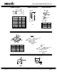
BW36 SERIES WOODBURNING FIREPLACE No one builds a better fire C. FIREPLACE SYSTEM COMPONENTS The table below, together with the following pictures, show only those components which may be safely used with this fireplace.
BW36 SERIES WOODBURNING FIREPLACE No one builds a better fire 217/8" 183/4" 335/8" 327/8" 111/2" 5 21" 71/4" 8" /8" 36" 385/8" 6" 1" 33/4" 71/4" 107/8" BW36C 335/8" 21" 327/8" 36" 385/8" 6" BW36 HEARTH EXTENSIONS 52" GLASS DOORS STRAIGHT ATTIC INSULATION SHIELD 16" 193/4" 24" HX3 BI-FOLD DOORS 351/2" DM1036 AS8 INSULATED DUCT INTEGRAL GRATES 4" 9 3 / 8" 42" ID4 175/8" UNINSULATED DUCT OUTSIDE AIR KIT GR16 4" 42" UD4 4" AK22 4-00 5 30491D
BW36 SERIES WOODBURNING FIREPLACE No one builds a better fire CHIMNEY SECTIONS CHIMNEY STABILIZER OFFSETS/RETURNS A 8" A 101/2" 8" 203/4" 21" HTI CAT.# A B SL306 6" 43/4" SL312 12" 103/4" SL318 18" 163/4" SL324 24" 223/4" SL336 36" 343/4" SL348 48" 463/4" 101/2" 6" 101/2" 8" HTI CAT.
BW36 SERIES WOODBURNING FIREPLACE No one builds a better fire CHIMNEY TERMINAL CAPS & VENT SECTIONS 167/8" 167/8" 153/4" 291/4" TR344 ROUND TERMINAL CAP WITH STORM COLLAR TR342 ROUND TERMINAL CAP 131/4" 143/4" 231/2" 161/2" 221/4" 23" (101/2" Outer) (8" Flue) 173/4" ST375 SQUARE TERMINAL CAP TS345/TS345P SQUARE TERMINAL CAP 72" 36" 7 10 /8" 2" CT35 CHASE TOP 4-00 7 30491D
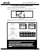
BW36 SERIES WOODBURNING FIREPLACE No one builds a better fire D. PRE-INSTALLATION PREPARATION 1. FIREPLACE LOCATIONS AND SPACE REQUIREMENTS. Several options are available to you when choosing a location for your fireplace. This fireplace may be used as a room divider, installed along a wall, across a corner or use an exterior chase. See Figure 1. In an exterior chase or projecting into a garage. As a room divider. Along a wall. Across a corner.
BW36 SERIES WOODBURNING FIREPLACE No one builds a better fire WARNING! TO PREVENT CONTACT WITH SAGGING OR LOOSE INSULATION, THE FIREPLACE MUST NOT BE INSTALLED AGAINST VAPOR BARRIERS OR EXPOSED INSULATION. LOCALIZED OVERHEATING COULD OCCUR AND A FIRE COULD RESULT. 2. FRAMING THE FIREPLACE. Figure 4 shows a typical framing (using 2 x 4 lumber) of the fireplace, assuming combustible materials are used. All required clearances to combustibles around the fireplace must be adhered to.
BW36 SERIES WOODBURNING FIREPLACE No one builds a better fire 3. HEARTH EXTENSIONS. A hearth extension must be installed with all fireplaces. It is to protect the combustible floor in front of the fireplace from both radiant heat and sparks. The construction of and materials used for a factorybuilt hearth extension are shown in Figure 5.
BW36 SERIES WOODBURNING FIREPLACE No one builds a better fire 4. SIDEWALLS/SURROUNDS. Adjacent combustible side walls must be located a minimum of 12" from the fireplace opening. See Figure 7. If you are using a decorative surround constructed of combustible material, it may be located within the shaded area defined in Figure 7. Short stub walls are also acceptable if they are contained within the shaded area. BRICK FRONT 4" FLUSH FRONT 12" 143/8" 50° A 3 9 /4" B 39° 12" CAT. # 12" MIN.
BW36 SERIES WOODBURNING FIREPLACE No one builds a better fire c. The “B” dimensions that coincide with the “A” dimensions represent the required vertical clearance that is needed to complete the offset and return. d. Read across the chart and find the number of chimney sections required and the model number of those particular chimney parts. A e. Whenever the chimney penetrates a floor/ceiling, a firestop spacer must be installed. f. The effective height of the firebox assembly is 335⁄8".
BW36 SERIES WOODBURNING FIREPLACE No one builds a better fire IF 10 FEET OR LESS 12" 12" MIN. TOP OF FIREPLACE OPENING THEN 335/8" Figure 8a - Fireplace (Side View) MUST BE AT LEAST 2 FEET 2. CHIMNEY HEIGHT REQUIREMENTS. (Above the roof line) BUT Major building codes specify a minimum chimney height above the roof top. These specifications are summarized in what is known as the “Ten Foot Rule”.
BW36 SERIES WOODBURNING FIREPLACE No one builds a better fire F. STEP-BY-STEP INSTALLATION OF THE FIREPLACE SYSTEM WARNING! BEFORE STARTING, DO THE FOLLOWING: 1. WEAR GLOVES AND SAFETY GLASSES FOR PROTECTION. 2. KEEP HAND TOOLS IN GOOD CONDITION. SHARPEN CUTTING EDGES AND MAKE SURE TOOL HANDLES ARE SECURE. 3. ALWAYS MAINTAIN THE MINIMUM AIR SPACE REQUIRED TO THE ENCLOSURE TO PREVENT FIRE. STEP 1 - Positioning the Fireplace.
BW36 SERIES WOODBURNING FIREPLACE No one builds a better fire STEP 4 - Assembling Chimney Sections. CAUTION: Attach either a straight chimney section or an offset to the top of the fireplace depending on your installation requirement. When using offsets and returns, we highly recommend securing in place on the top of the fireplace with screws to permanently attach them to the top of the fireplace. See Figure 11. INNER FLUE AND OUTER LINER SECTIONS CANNOT BE DISASSEMBLED ONCE LOCKED TOGETHER.
BW36 SERIES WOODBURNING FIREPLACE No one builds a better fire 141/2" AS8 ATTIC INSULATION SHIELD FS338 FIRESTOP SPACER INSULATION 24" CHIMNEY 101/2" WARNING! WHEN CHIMNEY SECTIONS EXCEEDING SIX FEET IN LENGTH ARE INSTALLED BETWEEN AN OFFSET/ RETURN, STRUCTURAL SUPPORT MUST BE PROVIDED TO REDUCE OFF-CENTER LOADING AND PREVENT CHIMNEY SECTIONS FROM SEPARATING AT THE CHIMNEY JOINTS. Figure 14 Installing an AS8 STEP 8 - Double-checking the Chimney Assembly.
BW36 SERIES WOODBURNING FIREPLACE No one builds a better fire STEP 12 - Assembling the Chimney Sections. STEP 15 - Completion of the Fireplace Enclosure. Continue to add chimney sections through the roof opening, maintaining at least a 2" air space. Complete the fireplace enclosure, allowing space for outside air ducts and gas piping if desired. Electrical wiring should not come in contact with the unit.
BW36 SERIES WOODBURNING FIREPLACE No one builds a better fire 1-1/2" clearance to combustibles Figure 18 Gas Knockout Location STEP 18 - Installing the Firescreen. Attach the firescreen to the fireplace side, utilizing the [2] hairpin clips in the columns. Use pliers to insert the clip through the last strand of screen wire and into the hole at the midpoint of the fireplace side. STEP 19 - Installing the Glass Doors.
BW36 SERIES WOODBURNING FIREPLACE No one builds a better fire 1. Materials for the Chase. The chase is constructed using framing materials much the same as the walls in your home. A variety of materials may be used including brick, stone, veneer brick, or standard siding materials. In constructing the chase, several factors must be considered. a. Maintain a 1" minimum air space around the firebox. b. Maintain a 2" air space around the chimney. c.
BW36 SERIES WOODBURNING FIREPLACE No one builds a better fire TR342 TERMINAL CAP CHASE TOP 18" MAX. DISTANCE INTENDED USAGE. This factory-built fireUPPERMOST CHIMNEY SECTION Figure 22 Installing a Terminal Cap place is intended for use with either solid fuel (firewood) or a decorative gas appliance that has been tested and listed to the Standard for Decorative Gas Appliances for Installation in Vented Fireplaces, ANSI Z21.60. When operating your fireplace, the flue damper must be in the open position.
BW36 SERIES WOODBURNING FIREPLACE STARTING THE FIRE. Check the flue damper to be certain it is in the full open position. Place crumpled or twisted paper under the fireplace grate. Loosely arrange kindling or small pieces of wood to form a layer above the paper. Light the paper and add small pieces of wood until a hot bed of embers has been established. At this point add progressively larger pieces of wood until you are able to position 4” diameter split logs as shown in Figure 23.
BW36 SERIES WOODBURNING FIREPLACE No one builds a better fire WARNING! Before starting a fire in your BW36 Series fireplace, use the following check list: FIREPLACES EQUIPPED WITH DOORS SHOULD BE OPERATED ONLY WITH DOORS FULLY OPEN OR FULLY CLOSED. IF DOORS ARE LEFT PARTIALLY OPEN, GAS AND FLAME MAY BE DRAWN OUT OF THE FIREPLACE OPENING, CREATING THE RISK OF BOTH FIRE AND SMOKE. FLUE DAMPER.
BW36 SERIES WOODBURNING FIREPLACE No one builds a better fire REMOVE (4) SCREWS AND LIFT TOP PAN OFF. LIFT UP TO REMOVE. SCREW 1. REMOVE THE 4 SCREWS. SCREW 2. REMOVE SCREEN. CAP CAP SLIP SECTION TR342, TR344 ROUND TERMINAL CAPS 3. REMOVE BAFFLE. CHASE ST375 SQUARE TERMINAL CAP TS345 SQUARE TERMINAL CAP Figure 25 Terminal Caps WARNING! CAUTION: A CHIMNEY FIRE CAN PERMANENTLY DAMAGE YOUR CHIMNEY SYSTEM. THIS DAMAGE CAN ONLY BE REPAIRED BY REPLACING THE DAMAGED COMPONENT PARTS.
WARRANTY FOR HEAT-N-GLO FIREPLACES The limited warranty will not become effective until you have mailed the completed warranty card to HEAT-N-GLO, A DIVISION OF HEARTH TECHNOLOGIES INC., 20802 Kensington Blvd., Lakeville, MN 55044. This card must be mailed within 60 days of the fireplace installation. Subject to the conditions set forth herein, Heat-N-Glo extends the following limited warranty with respect to your Heat-N-Glo fireplace, excluding accessories, Chimney components and Glass Doors.