
Gas Heater User Manual


16
!
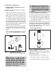
• Drill a hole or drive a nail through this center point.
• Check the floor above for any obstructions, such
as wiring or plumbing runs.
• Reposition the heater and flue system, if neces-
sary, to accommodate the ceiling joists and/or
obstructions.
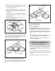
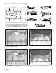
• Cut an 11-inch X 11-inch (280 mm X 280 mm)
hole through the ceiling, using the center point
previously marked.
• Frame the hole with framing lumber the same
size as the ceiling joists.
Figure 16 Hole and New Framing Members
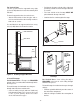
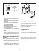
If the area above the ceiling is NOT an attic, position
and secure the ceiling firestop on the ceiling side of
the previously cut and framed hole.
Figure 17 Ceiling Firestop (Ceiling Side)
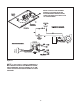
If the area above the ceiling IS an attic, position and
secure the firestop on top of the previously framed
hole.
Figure 18 Attic Firestop
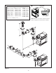
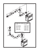
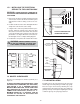
C. Flue Termination
For Horizontal Terminations - To attach and secure
the termination to the last section of horizontal flue:
• Rotate and interlock the ends as described at the
beginning of the Installing Flue Components sec-
tion.
• The termination kit should pass through the wall
firestops from the exterior of the building.
• Adjust the termination cap to its final exterior po-
sition on the building.
WARNING: THE TERMINATION CAP
MUST BE POSITIONED SO THAT
THE ARROW IS POINTING UP.
• Use the exterior pipelock hole provided on the
round flange of the wall firestop to secure the flue
pipe in place.
• Use a high-temperature sealant or fiberglass rope
gasket to seal between the pipe and exterior
firestop.
• See Figure 4 for flue termination clearances.
JOIST
CEILING FIRESTOP
CEILING
NAILS (4 REQUIRED)
CHIMNEY
HOLE
11”
(280mm)
11”
(280mm)
CEILING
NEW
FRAMING
MEMBERS
EXISTING
CEILING
JOISTS
CEILING
CEILING FIRESTOP
RAFTER
NAILS (4 REQUIRED)