Installation and Operation Manual Bulletin No.
Installation and Operations Manual Table of Contents Introduction............................................................................................................... 3 Inspection Unit Designation Model Definition Table 14. Oil Safety Switch...................................................................................... 22 Table 15. Part Load Performance Multipliers Table 16. Required Differential Pressure Three-Phase Voltage Monitor System Warranty........................................
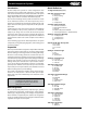
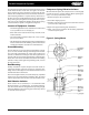
Parallel Compressor Systems Introduction Model Definition: Parallel Compressor systems are central refrigeration units employing 2 to 8 parallel piped compressors, a control panel, and receiver mounted on one common base frame. The system may be designed for either Indoor or Outdoor use. The Outdoor design may include the condenser mounted and piped. 1st digit - Brand (B, C, H, or L) The selection and design of the system is based on the needs of the individual customer.
Installation and Operations Manual System Warranty This equipment is designed to operate properly and produce the rated capacity when installed in accordance with good refrigeration practice.
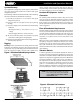
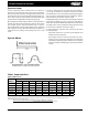
Parallel Compressor Systems absorbing spring mounts (optional equipment) must be placed under the base frame of each unit. See Figure 1 for view of Spring Isolator. The spring mounts are placed under the unit and the unit carefully lowered on to the mounts. Note that no other mounting hardware is required and any unevenness in the floor or uneven weight distribution may be compensated for by turning the spring mount leveling nuts with an openend wrench.
Installation and Operations Manual Unit Access Always provide sufficient clearance for unit maintenance and service. Minimum clearances for most situations are described below (except 60 Inches of free space is required in front of the control panel). Please note that these are minimums and more clearance may be required by local codes. Vertical Clearance Overhead obstructions are not permitted.
Parallel Compressor Systems Ventilation Requirements Indoor Units If compressors or condensing units are located in a machine room, adequate ventilation air must be provided to avoid an excessive temperature rise in the room. To allow for peak summer temperatures a 10°F temperature rise is recommended, although a 15°F rise might be acceptable. With compressors with remote condensers, approximately 10% of the heat rejected is given off by the compressor casting and the discharge tubing.
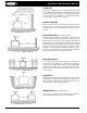
Installation and Operations Manual • In systems equipped with capacity control compressors, or where multiple compressors are used with one or more compressors cycled off for capacity control, double suction risers should be installed. See Figure 6 below. The two lines should be sized so that the total cross-section area is equivalent to the cross section area of a single riser that would have both satisfactory gas velocity and acceptable pressure drop at maximum load conditions.
Parallel Compressor Systems Expansion Loops In order to compensate for the expansion of the tubing, it is necessary to estimate the amount of expansion and then provide offsets or loops in the refrigerant piping. Normally the area to be most concerned with is the straight line distance from the fixture to the parallel compressor unit.
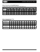
Installation and Operations Manual Table 2. Pressure Loss of Liquid Refrigerants (In Liquid Line Risers - Expressed in Pressure Drop, PSIG, and Subcooling Loss, °F) Liquid Line Rise in Feet Refrigerant 10’ 15’ 20’ 25’ 30’ 40’ 50’ 75’ 100’ PSIG °F PSIG °F PSIG °F PSIG °F PSIG °F PSIG °F PSIG °F PSIG °F PSIG °F R-12 5.4 2.8 8.1 4.2 10.7 5.4 13.4 6.9 16.1 8.3 21.5 11.3 26.9 14.3 40.3 22.4 53.7 31.0 R-22 4.8 1.6 7.3 2.3 9.7 3.1 12.1 3.8 14.5 4.7 19.
Parallel Compressor Systems Table 4. Weight of Refrigerants in Copper Lines During Operation (Pounds per 100 Lineal Feet of Type “L” Tubing) Suction Line at Suction Temperature Line Size OD (in.) Refrigerant Liquid Line Hot Gas Line -40°F -20°F 0°F 20°F 40°F 3/8 12, 134A 22 R-507, 502, 404A 4.0 3.9 3.4 .15 .22 .31 .01 .02 .03 .01 .03 .04 .02 .04 .06 .04 .06 .09 .06 .08 .13 1/2 12, 134A 22 R-507, 502, 404A 7.4 7.4 6.4 .30 .41 .58 .01 .03 .04 .03 .05 .07 .04 .07 .13 .07 .11 .16 .
Installation and Operations Manual Table 5A.
Parallel Compressor Systems Table 5B.
Installation and Operations Manual Table 6A.
Parallel Compressor Systems Table 6B.
Installation and Operations Manual Table 7. Recommended Remote Condenser Line Sizes R-12 & R-134A R-22 R-502 R-507 & R-404A Liquid Line Liquid Line Liquid Line Liquid Line Net Total Discharge Discharge Discharge Discharge Cond. to Cond. to Cond. to Cond. to Evap. Equiv.
Parallel Compressor Systems Leak Checking, Evacuation and Start-up Warning: It is illegal to knowingly vent or discharge any CFC’s and HCFC’s to the atmosphere. ALL CFC’s and HCFC’s must be reclaimed or recycled. 4. With all compressor and control breakers and toggle switches turned off, apply power to the unit. If the unit is using a phase monitor, the green light must come on before going any further. (See instructions for phase protector elsewhere in this manual.
Installation and Operations Manual Refrigerant Distribution The distribution system is selected based upon the type of defrost for that particular system. For each set of liquid/suction lines a distribution system must be selected. Liquid solenoids are recommended to be installed at the evaporator on all systems, particularly systems with long line runs. The solenoid will prevent continued feed to the evaporator through the expansion valve when it is not in operation.
Parallel Compressor Systems Electronic Control System The electronic controller has become the standard on parallel compressor systems. The increased capabilities of the controllers magnify the efficiency of the parallel compressor system making it a very attractive accessory item. The electronic control system preferred by Heatcraft is the Computer Process Control (RMCC) controller. The RMCC offers a complete control and monitoring package through one or more input boards (16AI).
Installation and Operations Manual Compressors The majority of the Heatcraft Parallel systems incorporate the Copeland compressor. Other brand compressors are available upon customer request. The compressors are solid mounted to a base frame or mounted on the refrigerant receiver. All reciprocating compressors incorporate oil floats. Crankcase heaters will be installed and wired.
Parallel Compressor Systems Table 11. Oil Safety Switch Copeland Part No. 085-0062-00 085-0088-00 085-0101-00 MFGRS. Model No. Penn Ranco Robertshaw Robertshaw Penn Robertshaw Sentronic P45NCA-12 P30-5826 PD21-2502 PD21-1006 P45NCB-3 LG21-2501 Pressure Diff. Psi (bar) Cut-In Cut-Out 7–9 12 - 14 9 (± 2) 14 Alarm Circuit Yes No Yes No Yes Yes Yes All controls are Manual Reset type with a 120 second nominal time delay at the rated voltage Table 12.
Installation and Operations Manual Table 14. Oil Safety Switch Carlyle Part No. Danfoss Part No. 634-2008 OR P529-2130 60B2101 634-2050 OR P529-2100 60B2151 Carlyle Part No. Johnson Part No. Time Delay O6DA660115 P345 45 sec. Pressure Diff. Psi (bar) Time Delay 45 sec. Reset Cut-In Cut-Out 8 – 11 (.55 - .76) 4-8 (.28 - .55) Manual Pressure Diff. Psi (bar) Reset Cut-In Cut-Out 8 – 11 (.55 - .76) 4-8 (.28 - .55) Manual Table 15.
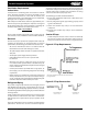
Parallel Compressor Systems Sight Glass & Moisture Indicator Figure 11. Direct Type Relief Valves The sight glass/moisture indicator helps determine that a unit has sufficient refrigerant charge and/or when the liquid line filter drier cores need to be replaced. Bubbles in the glass may indicate a shortage of refrigerant or a restriction in the liquid line (i.e. plugged liquid line filter drier).
Installation and Operations Manual Table 17. Henry Relief Valve Capacity Rating Type Standard Pressure Settings PSIG Inlet Outlet 350 400 425 450 526E 3/8 MPT 3/8 FLARE 10.2 11.6 12.3 13.0 527E 1/2 MPT 5/8 FLARE 28.5 32.4 34.4 36.3 Angle Straight Through Size Connection Catalog Number 5231 3/8 MPT 3/8 FLARE 11.2 12.7 13.5 14.3 5231-A 3/8 MPT 1/2 FLARE 18.6 21.1 22.4 23.7 5231 1/2 MPT 5/8 FLARE 18.6 21.1 22.4 23.7 5232 1/2 MPT 5/8 FLARE 28.1 32.0 33.9 35.
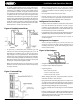
Parallel Compressor Systems Series P100 Pressure Control Liquid Level Switch The P100 series, manufactured by Johnson Control, Inc., are encapsulated, non adjustable, single-pole single throw, direct mount pressure controls typically used for low or high pressure cutouts. On the Heatcraft manufactured parallel systems, the control is used for High Pressure cutout. S-9400 Level Switch Series There are two types available. Auto Reset Models and Manual Reset Models. Figure 13.
Installation and Operations Manual Module Replacement Low Pressure Oil System 1. Disconnect power at the fuse box 2. Remove wiring box from the retainer 3. Remove the IRR 4000-93 Ring with an IRR P-101 or equivalent retaining ring pliers 4. Remove the Retainer 5. Pull out the module by the leads 6. Install new Module 7. Verify the voltage rating 8.
Parallel Compressor Systems to the compressor. Temprite Valve Adjustment Before the oil separator is installed, an initial charge of oil must be added to it. This initial charge of oil is the amount that is needed to just float the needle valve float. This amount of oil will stay in the oil separator when in operation and will seal the needle and prevent damage to the float mechanism. Oil Precharge is very important.
Installation and Operations Manual Table 22. AC&R Model Regulators AC&R Model No. Connection Size Operation Pressure Diff., psig Oil Level, Sight Glass S-9010 3 BOLT 5 - 30 1/2 S-9010A 4 BOLT 5 - 30 1/2 S-9015 3/4” NPTF F.
Parallel Compressor Systems Suction Filter Replaceable core suction filters are supplied as standard on all units. The flanged shell holds replaceable pleated filter elements suitable for installation in the suction line of refrigeration systems. In this way any contaminants left in the system at start-up can be removed before they circulate back to the compressor. The suction filters are shipped loose for field installation. (See No. 3 of Leak Checking, Evacuation, and Start-up section in this manual).
Installation and Operations Manual Superior Valve Company Table 28. Type AFD (for cleanup) Replaceable Cartridges - Replaceable Suction Filter • On many parallel systems, the Superior Valve Co. suction filter is installed. Table 25. Type F Filter Replaceable Cartridges Shell No. Catalog No. IBCA No. Cartridge OD (in.) Filter Area (in2.) 2CFA F25A 51071 1-23/32 66 3CFA F35A 51072 2-5/8 115 4CFA F45A 51073 3-17/32 189 5CFA F55A 51074 4-1/16 270 Table 26.
Parallel Compressor Systems Liquid Drain Control Method This method is ideal for large capacity systems since a smaller regulator is required for liquid line than for discharge line. During warm ambient temperature conditions valves A and C will be open and Valve B will be closed. When the ambient temperature at the condenser drops, the condenser pressure will tend to become lower.
Installation and Operations Manual must be varied during the setting procedure and it is difficult to determine exactly when the bypass valve opens unless a pressure gauge can be located at the valve outlet. Therefore, sufficient load must be available in some form to raise the suction pressure above the desired valve setting.
Parallel Compressor Systems General Maintenance Schedule (Service/Maintenance should be performed only by a qualified / certified refrigeration service technician.
Installation and Operations Manual SERVICE DIAGNOSIS CHART Symptom Compressor Does Not Run Cause Remedy 1. 2. 3. 4. 5. Motor Line open Fuse blown Tripped overload Control contacts dirty or jammed in open position Piston seized 1. 2. 3. 4. 5. 6. Frozen compressor or motor bearings 6. 1. 2. 3. Control differential set too close Discharge valve leaking Motor compressor 1. 2. 3. 4. 5. 6. Refrigerant shortage Refrigerant over charge Cycling on high pres. cutout 4. 5. 6. 1. 2.
Parallel Compressor Systems Symptom Cause Remedy Low Discharge Pressure 1. 2. 3. 4. 5. Insufficient refrigerant in system Faulty condenser temp. regulation Compressor suction or discharge valve inefficiencies Low suction pressure Head pressure control valve set wrong or no head pressure control valve 1. 2. 3. 4. 5. Check for leaks.
SERVICE RECORD A permanent data sheet should be prepared on each installation, with a copy for the owner and the original for the installing contractor’s files. If another firm is to handle service and maintenance, additional copies should be prepared as necessary. System Reference Data The following information should be filled out and signed by the Refrigeration Installation Contractor.