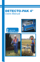
DETECTO-PAK 4® Users Manual
Proprietary Notice The contents of this manual are proprietary to Heath Consultants Incorporated. Reproduction of this manual, in whole or in part, is prohibited without the express written consent of Heath Consultants Incorporated. Heath Consultants Incorporated operates under a continual product improvement program and reserves the right to make improvements and/or changes without prior notification. This manual supersedes all previous manuals for the Heath Detecto-Pak 4.
Detecto-Pak® 4 Users Manual Heath Consultants Incorporated Houston, TX 713-844-1300 Fax: 713-844-1309 1-800-HEATH-US www.heathus.
TABLE OF CONTENTS INTRODUCTION ……..............................…………………………………. .ii FUNCTION ….............................…………………………………………… iii WARNINGS ...........................................……………………………………. .iv CHAPTER ONE I. PROCEDURES DETECTO-PAK 4 PROCEDURES…………........................……… 1 CHAPTER TWO FUEL CYLINDERS II. FUEL MOTHER TANKS, FUEL CYLINDERS …......................…. 6 CHAPTER THREE CALIBRATION CYLINDERS III. CALIBRATION MOTHER TANKS, CALIBRATION CYLINDERS …........................
INTRODUCTION The HEATH Detecto-Pak 4 Flame Ionization Hydrocarbon Detector is designed to withstand normal field use and provide sensitive indication of the presence of hydrocarbon vapors. This instruction manual is divided into nine chapters. Each chapter is designed to assure that the operator will obtain the best use of the Detecto-Pak 4. Chapter One, Detecto-Pak 4 features, should be required reading for all operating personnel prior to using the DetectoPak 4.
FUNCTION The Heath Detecto-Pak 4 Flame Ionization Hydrocarbon Detector is designed to detect and measure the presence of hydrocarbons (calibrated for methane). The instrument has five sensitivity ranges: 10, 50, 100, 1,000 (1K), and 10,000 (10K) ppm (1% gas). This instruction manual describes the operation of the instrument and provides limited maintenance information. Heath firmly believes the Detecto-Pak 4, when properly maintained, will provide reliability and ease of operation for many years.
WARNING EXPLOSIVE GAS MIXTURES CAN CAUSE SERIOUS INJURY OR DEATH. INHALATION OF VAPORS CAN CAUSE HEALTH IMPAIRMENT. WARNING IT IS ESSENTIAL THAT USERS OF THIS INSTRUMENT READ, UNDERSTAND, AND FOLLOW THE INSTRUCTIONS FOR OPERATION AND MAINTENANCE AND THE PRECAUTIONS CONTAINED IN THIS MANUAL TO ENSURE THE INSTRUMENT IS USED IN A PROPER AND SAFE MANNER. WARNING DO NOT ATTEMPT TO REPAIR THE INTERNAL FUEL REGULATOR. DISASSEMBLY COULD CAUSE DAMAGE TO THE DETECTO-PAK 4.
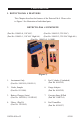
CHAPTER ONE I. DETECTO-PAK 4 FEATURES This Chapter describes the features of the Detecto-Pak 4. Please refer to Figure 1 for illustration of individual parts. DETECTO-PAK 4 COMPLETE (Part No. 100659-0, 110 VAC) (Part No. 100659-2, 220 VAC) (Part No. 100659-1, 110 VAC High Alt.) (Part No. 100659-3, 220 VAC High Alt.) (Part No. 100659-4, 0-100K) (Figure 1) 1. Instrument Only (Part No. 100581-0, 100581-1) 5. Fuel Cylinder (2 included) (Part No. 0618303) 2. Probe, Sample (Part No. 0111006) 6.
PROCEDURES 1. INSTRUMENT Sensitivity Ranges: Audible Alarm, continuous: 0-10, 0-50, 0-100, 0-1,000 (1K), and 0-10,000 (10K) ppm Continuous alarm indicates flame is out. Audible Alarm, pulsating: Fuel Cylinder Pressure Indicator: Pulsating alarm indicates signal level above approximately 35 to 45% full meter scale. Fuel Regulator, Internal: Inlet Pressure, 0 - 1,750 psig; Outlet Pressure, 22 - 42 psig; factory set for 30 cc/min fuel flow with 1,000 psig in fuel cylinder.
PROCEDURES 5. FUEL CYLINDERS Color: Black, DOT Rated 3E1800 Volume: 100 cubic centimeters (approximate) Maximum Working Pressure: 1,750 psig Weight: 1 lb. (.453 kg) 6. GAUGE ADAPTER Gauge Adapter is used to indicate outlet pressure setting of internal regulator. Weight: 5.6 oz. (.159 kg) 7. CARRYING STRAP WITH PAD Strap: Weight: Strap facilitates carrying instrument over shoulder with cushioning pad. 6.4 oz. (.181 kg) 8. FUEL TRANSFILLER (Part No.
PROCEDURES ADDITIONAL FEATURES (not shown) • Instruction Manual • “O” Rings for fuel cylinder valve: Dimensions .145 ID x .070 CS inches Material: Buna-N • “O” Ring Lubricant: Lubricant supplied for “O” Rings for fuel cylinder valves. • Sample Intake Rate: Pump, 2,000 cc per minute, (2 SLPM) nominal • Ignition Type: Glow Coil • Battery Indicator: Needle indication (three color) on instrument ppm meter shows battery status.
PROCEDURES OPTIONAL ACCESSORIES Calibration Kit This Calibration Kit is available to field calibrate the With Gas: Detecto-Pak 4 to ensure proper sensitivity levels, and comes complete with Calibration Gas Cylinder. (Part No. 0123309-0). Calibration Gas: Calibration cylinder filled to approx. 1500 + 200 psig of 100 + 10 ppm methane, balance air, to use with above calibration kit. (Part No.
CHAPTER TWO II. FUEL MOTHER TANKS/FUEL CYLINDERS: This Chapter discusses, in detail, the proper steps to take in transferring fuel to the fuel cylinder. Recommendations for ordering fuel mother tanks, along with proper storage, are also discussed in detail. A. FUEL GAS MIXTURE The fuel gas is a certified mixture of 40% hydrogen/60% nitrogen +/- 2% with less than .5 ppm of hydrocarbon. B. TRANSFILLING FUEL CYLINDERS Heath assumes no liability in refilling of fuel cylinders.
FUEL CYLINDERS MOTHER TANK, TRANSFILLER & FUEL CYLINDER CONNECTED FOR TRANFILLING Fuel Cylinder Transfiller Mother Tank 1. (Figure 2) Remove the safety cap or caps from the fuel mother tank. 2. Very slowly, open valve on the fuel mother tank a very small amount (crack). Then close it immediately. This will clean (blow) any contaminants out of the valve. 3. Firmly secure the hex nut on the transfiller to the fuel mother tank valve outlet using an appropriate wrench.
FUEL CYLINDERS level (determined by fuel mother tank internal pressure). DO NOT EXCEED 1750 psig pressure in the fuel cylinder. 8. Open bleed off valve on transfiller to eliminate pressure in transfiller. 9. Loosen knurled nut with finger pressure and remove fuel cylinder. 10. Remove transfiller from fuel mother tank, replace safety cap or caps, and safely store fuel mother tank. For storing and transporting of these fuel mother tanks/fuel cylinders, see Paragraphs D. and E. of this Section. C.
FUEL CYLINDERS **NOTE** The need for a special mixture of high altitude fuel for operations located 3,000 feet or more above sea level may arise. When these circumstances occur, please contact the Heath representative in your area for assistance. (See Chapter Five, Section V - B, IMPORTANT, covering high altitude operation for special instructions.) D. STORING FUEL MOTHER TANKS OR CYLINDERS The fuel mother tanks or fuel cylinders must be stored in accordance with D.O.T. and/or OSHA regulations.
CHAPTER THREE III. CALIBRATION MOTHER TANKS/CALIBRATION CYLINDERS: This Chapter discusses, in detail, the proper steps to take in transferring calibration gas to a calibration cylinder. Recommendations for ordering calibration gas mother tanks, along with proper storage, are also discussed. A. CALIBRATION GAS MIXTURES The calibration gas is comprised of a mixture of 100 ppm + 10% methane, balance zero air.
CALIBRATION CYLINDERS MOTHER TANK, TRANSFILLER & CALIBRATION CYLINDER CONNECTED FOR TRANSFILLING (Figure 3) 1. Remove the safety cap or caps from the calibration mother tank. 2. Very slowly, open valve on the calibration mother tank a very small amount (crack). Then close it immediately. This will clean (blow) any contaminants out of the valve. 3. Firmly secure the hex nut on the calibration transfiller to the calibration mother tank valve outlet using an appropriate wrench.
CALIBRATION CYLINDERS 8. Open bleed off valve on calibration transfiller to eliminate pressure in calibration transfiller. 9. Loosen small hex nut and remove calibration cylinder. 10. Remove calibration transfiller from calibration mother tank, replace safety cap or caps, and safely store calibration mother tank. C. ORDERING CALIBRATION MOTHER TANKS OR CALIBRATION CYLINDERS Calibration mother tanks/calibration cylinders are available from Heath at the listed location.
CHAPTER FOUR IV. CHARGING SYSTEMS The Detecto-Pak 4 Flame Ionization Detector utilizes a 1.5 amp hour Nickel Metal Hydride rechargeable battery pack as the source of its power. The instrument was designed for 8 hours of continuous operation however this battery, when properly cared for, will provide adequate power to operate the instrument for 10 plus hours under normal conditions. In freezing conditions the battery capacity is reduced between 10% and 20% depending on the health of the battery.
B. BATTERY CHARGER It is very important to use ONLY the approved charger supplied with the Detecto-Pak 4 to recharge the battery pack. Substitute chargers may damage the battery pack. After the charger has been plugged into the Detecto-Pak 4 for 10 hours, the charger will automatically reduce itself to the float mode. The float mode will maintain a charge in the battery as long as it is connected to the charger. We recommend the Detecto-Pak 4 be connected to the charger whenever it is not it use.
2. Put the nickel metal hydride battery through a charge/discharge cycle at least once a month when the instrument is not in use. Nickel metal hydride batteries function best when frequently used. 3. Only use a Heath supplied nickel metal hydride battery and accompanying approved battery charger as they are matched for optimum performance and safety. 4. Do NOT use a nickel metal hydride battery when it is fully discharged. When the battery is depleted, it must be recharged before use. 5.
CHAPTER FIVE V. OPERATING THE DETECTO-PAK 4 This Chapter explains and contains a detailed illustration of the control panel. Operating and shutdown procedures are also discussed. Detecto-Pak 4, Instrument Only, Part No. 100581-0, 100581-1 (Figure 4) 1. Fuel Gauge 2. Ignition Switch 11. Meter 3. Meter Lamp Switch 12. Alarm LED 4. Range Up/Down Switch 13. Zero Up/Down Switch 5. Signal Alarm Switch 14. 6. Low Flow Alarm LED 15. Signal Alarm 7. Power Switch 16. 8.
Operation A. INSTRUMENT LAYOUT AND CONTROLS. 1. FUEL GAUGE: Mechanical fuel gauge used to indicate the pressure in the fuel cylinder. 2. IGNITION SWITCH: Pressing firmly down on the ignition switch produces voltage across the coil in the detector cell to ignite the air/ fuel mixture. 3. METER LAMP SWITCH: Press to enable meter lamp for backlight. 4. RANGE UP/DOWN SWITCH: These two switches are used to select the respective ppm range.
Operation Pressing the switch again will shut off the fuel flow to the detector cell which will extinguish its’ flame. The instrument will then automatically turn off. 8. RANGE LEDs: Blinking LEDs used to indicate the selected ppm range. 9. EXTERNAL PRESSURE GAUGE CONNECTOR: Used to check the internal regulator output pressure with an external pressure gauge. 10. SAMPLE INLET/FILTER HOLDER HOUSING: The hose from the Sample Probe connects to the instrument at this location.
Operation 15. SIGNAL ALARM: Audible alarm used to indicate the various types of alarm conditions which may exist. A continuous alarm is used for flame out, low sample flow, or in the rare event of detector cell over-heating. A pulsating alarm is used for indicating the signal level exceeds the alarm set point. 16. Please use Heath supplied charger only to charge DP4 through this charger jack. **NOTE** The instrument will verify all control switch operations by making a short beep.
Operation 4. Insert the fuel cylinder into the cylinder holder at the rear of the instrument. Turn the cylinder clockwise until the high pressure gauge moves upscale. Turn cylinder an additional 1/4 to 1/2 turn, or until snug. Do not over-tighten the cylinder. 5. Replace the sample inlet filter if dirty, contaminated, or wet. A clean filter should always be inserted in the filter cup prior to each use. Replace filter daily or more often if required.
Operation 13. To check pulsating signal alarm operation by press zero up switch until pulsating alarm sounds. Allow time for the meter to settle. The pulsating alarm should turn on at a meter reading between 35-45% of full scale. Return meter reading to zero. 14. To verify that the instrument is operational, the Detecto-Pak 4’s sensitivity should be tested by introducing a small sample of a known hydrocarbon gas to the sample inlet. The meter should swing upscale and return to zero. 15.
Operation f. Select the 10 ppm range and fine zero the instrument using the zero controls on the top panel. Press and release a zero control to make adjustments. Wait at least one second between zero control presses. **NOTE** While in operation, it is normal for the zero to drift with ambient temperatures and small changes in the methane background concentration. The fine zero controls also support a “fast” mode equal to 10 single presses.
CHAPTER SIX VI. CALIBRATION: The Heath Detecto-Pak 4 is factory calibrated. It is recommended that the Detecto-Pak 4 be calibrated once a week. However, it is recognized that the Detecto-Pak 4 will be used for a wide range of applications and for varying lengths of time. Such variables may cause the operator to develop his or her own calibration schedule. The operator may see a need for a more or less frequent calibration schedule.
CALIBRATION B. CALIBRATION PROCEDURES (Figure 6) **NOTE** A calibration kit & calibration cylinders are available to calibrate the Detecto-Pak 4. Any other method will not insure proper calibration levels. Allow instrument to warm up 15 minutes prior to calibration. 1. Start with the Detecto-Pak 4 in operation as described under “OPERATING PROCEDURES.” (See Chapter Five, Section V, B) 2. Set the instrument on a flat, horizontal surface.
CALIBRATION 7. Attach calibration kit regulator assembly to calibration cylinder; turn calibration cylinder valve knob counterclockwise (one-half to one turn). DO NOT FORCE THE KNOB ALL THE WAY COUTERCLOCKWISE (OPEN) 8. Attach calibration kit outlet connector to the portable unit by pushing the connector firmly into the sample inlet quick connector on the filter housing. Within 30 seconds, the meter needle should start moving upscale. Allow another one-half minute (30 seconds) before checking the meter.
CALIBRATION IMPORTANT Special procedures must be followed when using the Detecto-Pak 4 at high altitudes (over 3,000 feet above sea level). A slightly richer fuel mixture (42% hydrogen/58% nitrogen) and increased fuel and sample flow rate (50-55 cc/m and 850 cc/m, respectively) are required. The instrument must be calibrated at elevation and re-calibrated if the elevation changes by 1000 feet or more.
CALIBRATION Front and rear view of the Detecto Pak 4 Access Ports (Figure 7) Location of the Access Ports Left Meter Calibration Port Right Course Zero Port (Figure 8) Rear View of the Detecto-Pak 4 PCB 100786-0 Rev.
CHAPTER SEVEN VII. APPLICATIONS FOR THE DETECTO-PAK 4 The Detecto-Pak 4 is a non-specific hydrocarbon detector. Its use as a hydrocarbon leak detector has many applications. This Chapter lists some of the various types of inspections and areas, which might be surveyed using this instrument. A.
APPLICATIONS F. HOUSING AUTHORITIES/APARTMENT COMPLEXES/ MOBILE HOME PARKS/MASTER METER FACILITIES Inspection of On-site Gas Lines and Services Customer Leak Complaints G. SANITARY LANDFILL/WASTE STORAGE/ ENVIRONMENTAL STUDY AREAS Hydrocarbon Contamination Inspection Head Space Analysis Sites Leaking Storage Tank Monitoring Perimeter Inspections 100786-0 Rev.
CHAPTER EIGHT VIII. MAINTENANCE INFORMATION TROUBLESHOOTING PROCEDURES AND PERIODIC MAINTENANCE This chapter deals with troubleshooting procedures and periodic maintenance. Each instrument utilized for leak detection and evaluation should be operated in accordance with the manufacturer’s operating instructions. 1. Instrument should be periodically “checked” while in use to ensure that the recommended voltage requirements are available. 2.
MAINTENANCE internal regulator set screw clockwise to increase the gauge pressure or counterclockwise to decrease the gauge pressure until it matches the sticker set point pressure. Re-install the plastic hole plug. A. TROUBLESHOOTING THE INSTRUMENT In the event the Detecto-Pak 4 fails to perform satisfactorily, look through the following list to try to find the reason for the malfunction and its corrective action.
MAINTENANCE 3. PORTABLE UNIT WILL NOT OPERATE FOR FULL EIGHT HOURS a. The fuel cylinders may not have been filled to recommended pressure (1,750 psig maximum). Try refilling the cylinders. b. There may be a leak between the fuel cylinder valve and regulator. Check “O” ring on valve stem. c. The rechargeable battery may not have been fully charged. Recharge battery per instructions in Chapter Four. B. FILTER REPLACEMENT 1. Unscrew bottom half of white plastic filter housing. 2.
MAINTENANCE C. PARTS LIST Part No.
MAINTENANCE 0111690 8300322 0114732 0114733 9990009 0514937 0123227 0123328 0518133 0518134 3515094 0618303 0618353 0110163 0110683 ADAPTER, SLEEVE, SAMPLING PROBE HOSE BARB, 1/8MPT*1/8 HOSE, BRASS HANDLE, PROBE INNER STEM PROBE DOW CORNING 111 LUBRICANT TRANSFILLER, FUEL GAUGE, 0-3000PSI 1.
CHAPTER NINE IX. SERVICE INFORMATION: A. WARRANTIES AND WARRANTY REPAIR All instruments and products manufactured by Heath Consultants Incorporated and its Heath Manufacturing Division are warranted to be free from defects in material and workmanship for one (1) year from the date of shipment. In addition, the Heath Pipe and Cable Locator (Sure-Lock) product line is warranted for two (2) years and the Plunger Bar (handles) is warranted for 90 days.
The following suggestions will expedite the repair of your instrument: • Package carefully, using the original shipping carton if available, and return all components. • Specify your complete shipping and billing addresses. • Specify the instrument or product name, model number, and serial numbers on all correspondence. • Include a brief description of the problem you are experiencing and specify the person to be contacted for information.
CUSTOMER ASSISTANCE, MANUFACTURING AND SERVICE LOCATIONS CORPORATE HEADQUARTERS Heath Consultants Incorporated 9030 Monroe Road Houston, Texas 77061 Phone: (713) 844-1300 Fax: (713) 844-1309 MANUFATURING AND WARRANTY SERVICE CENTERS Heath Consultants Factory Service Center 9030 Monroe Road Houston, Texas 77061 Phone: (713) 844-1350 Fax: (713) 844-1398 DIVISION OFFICES Northeast Region 1051 Garden Street Greensburg, PA 15601 Phone: (724) 836-7830 Fax: (724) 836-7835 Central Region 9030 Monroe Road Houston, T
GLOSSARY CGA Compressed Gas Association calibration the act of fixing or correcting the graduations of a measuring instrument ceramic flame orifice inert, high temperature-resistant ceramic opening on the unit that allows shaping of the flame for greater reliability contaminants impure or corrupting substances D.O.T.
Nickel metal hydride battery (NiMH) a battery with its elements primarily composed of nickel, a silver-white metallic element, and cadmium, a metallic chemical element used in alloys nonflammable not easily set on fire non-specific not pertaining to a specific kind or type optimum most favorable or best ohm unit of electrical resistance OSHA Occupational Safety and Health Administration ppm range range showing parts per million preclude make imp
INDEX A B C D, E, F G H, I Additional Features, p. 4 Battery charger, p. 13 Battery Charger, p. 3 Calibration gas , p. 22 Calibration Gas Mixture, p. 10 Calibration procedures, p. 22 Carrying Case, System, p. 3 Carrying Strap with Pad, p. 3 Charging procedure, p. 14 Controls , p. 15 Customer assistance, manufacturing and Service locations, p. III Figure 1, p. 1 Figure 2, p. 7 Figure 3, p. 11 Figure 4, p. 15 Figure 6, p. 24 Figures 7 & 8, p. 26 Filter replacement, p. 31 Fuel Cylinders, p.
P Q, R, S T Parts list, p. 32 Probe, Sample, p. 1, 2 Shipping calibration mother tanks or cylinders, p. 12 Shipping Fuel Mother Tanks Cylinders, p. 9 Shutdown procedures, p. 21 Storing calibration mother tanks or cylinders, p. 12 Storing Fuel Mother Tanks or Cylinders, p. 9 Transfilling Calibration Cylinders, p. 10 Transfilling Fuel Cylinders, p. 6 Troubleshooting the instrument , p. 29 U, V, W,X, Y, Z Warranties and warranty repair, p.
Heath Consultants Incorporated operates under a continual product improvement program and reserves the right to make improvements and/or changes without prior notification. Heath Consultants Incorporated Houston, TX 713-844-1300 Fax: 713-844-1309 1-800-HEATH-US www.heathus.com Heath...