Heath Volume Corrector HVC 325 Series User’s Manual & Field Installation Guide Heath Consultants Inc. Houston, TX 713-844-1300 Fax: 713-844-1309 1-800-HEATH-US www.heathus.
325 IS Series HVC User’s Manual & Field Installation Guide Proprietary Notice The contents of this manual are proprietary to Heath Consultants Incorporated. Reproduction of this manual, in whole or in part, is prohibited without the express written consent of Heath Consultants Incorporated. Heath Consultants Incorporated operates under a continual product improvement program and reserves the right to make improvements and/or changes without prior notification.
Table of Contents 325 IS Series ................................................................................................................................... 2 Heath Volume Corrector (HVC) Overview .................................................................................... 4 HVC Features ...............................................................................................................................4 Mounting & Installation .......................................................
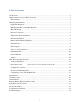
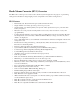
Heath Volume Corrector (HVC) Overview The HVC 325 is a microprocessor based, self-contained system designed for the purpose of performing ideal gas law calculations using integral pressure, temperature and volume sensing devices.
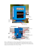
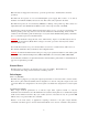
Display Uncorrected mechanical index Scroll Button Earth Ground Stud Drill spot faces front of the meter Optional Transducer #2 (not yet available) ( Pressure port ( External Modem Wiring Port Locking Hasp Optional Temperature Probe Port RS232 PC Com port Universal mounting plate Figure 1: LCD Display List: Corrected Volume (default after 4 minutes)/ Uncorrected Volume/ Correction Factor/ Gas Pressure/ Gas Temp/ Main Battery Voltage/ Backup Lithium Voltage/ Active Alarms.
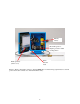
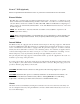
Primary battery Reversible gears for adapting to CW or CCW rotating meters Earth Ground Stud Back up battery (under cover) Figure 2: Inside configuration. Refer to drawing MTM-308-1 for field wiring requirements for external power and modem connections to maintain intrinsic safety.
Mounting & Installation Equipment Required • • • • • • Lap Top Computer (Using Win XP, Win Vista or Win 7) Communications Cable Test Gauge, Dead Weight Tester or Accurate Pressure gauge Temperature Reference (If equipped with gas temperature probe) HVC Mounting Kit (gasket, wrench) Mechanics Tool Kit Matching the HVC to the Meter Rotation The HVC 325 is equipped with a “Falling magnet/ reed switch” Mechanical Index Assembly.
Pressure Connection Connect the pressure (or gas) supply to the 1/4” NPT female connector located on the back of the HVC 325 housing. After piping is complete, check all connections to ensure that no leaks are present. Note: For ease and isolation of testing, the HVC large mounting kit is recommended. This kit will assist in future calibrations and inspection while the unit is in service.
HVC 325 units are shipped from the factory, powered up and ready to install (Unless otherwise specified). The HVC 325 incorporates an on board uninterruptible power supply. This consists of one factory installed “AA” lithium cell (BT1) rated at 3.6 volts. This cell is easily replaced in the field. The HVC incorporates an on board battery (CR2032) for backup of the profiler log. This consists of a replaceable button style lithium battery (BT2) located on the component side of the PCB.
Form “C” PCB (Optional) This is an optional feature that adds two Form “A” pulses for Corrected and two for Uncorrected. External Modem The HVC 325 is equipped with two RS232 communication ports. “Com Port 1” is dedicated to local direct communication at 19200 baud using the HVC “comm cable”. “Com Port 2” is used for connecting a modem. Remote baud rates available are 300, 1200, 2400, 9600 and 19200.
HVC HOST Operating Software HVC Host is the companion software interface to the HVC instrument. The application program provides for configuration, calibration, local and remote communication, interrogation, data collection and data processing. The Auto Download feature allows automatically polling any or all the instruments (on remote communications- modems or TC/IP) from a “Master Directory” list. This “Auto Download” feature is included in the HVC Host and is supplied on CD ROM media.
Quick Start Guide Note: Click “F1” key for help on any item. 1. Install the HVC Host software from the CD software disk provided. 2. Setup “Host Setup” (Com 1, 19200, Direct, is most common). If your com port is different than com 1 (or you are using a USB to serial adapter, find out the port number and select it). Make sure to use the same USB port every time. 3. Make any other changes to the Host Setup. Click OK. 4. Connect the communication cable from the PC to the back of the instrument. 5.
Configure 1 Screen * Meter Drive (Input Scale Factor)= (X1, X5, X10, X100, X1,000, X10,000) Should correspond to the amount of uncorrected gas per revolution of the meter. * Uncorrected Volume Display Scale Factor= (X1, X5, X10, X100, X1,000, X10,000) Sets the scale for all Uncorrected volume displays throughout the system (LCD, Display1, Profiler etc.
* Uncorrected Volume/ Leading blanks or Leading zeros = Sets either “Leading Blanks” or “Leading Zeros” on the LCD. * Meter Factor = (Manual entry) Applies a correction factor to the input pulse count. This can correct for a “Known and predictable” meter error. Allowable range is .95 to 1.05 (+ or – 5%). * Turbine K Factor = (Manual entry) Allows entering a K factor from an electronic turbine meter (Currently this option pcboard is not available at this time).
* FPV Mode = (Auto or fixed). Use “Auto” to calculate FPV based on the configurations of the instrument. Use “Fixed” when using fixed factor measurement or there is a need to lock in a specific FPV for calculation. * Instrument Units = (US or Metric) When configured to US units the unit will display in Cubic Feet for Volume/ PSI for Pressure/ Degrees F for temperature. When configured to Metric units the unit will display in Cubic Meters for Volume/ KPA or BAR for Pressure/ Degrees C for temperature.
DOWNLOADING AND PRINTING DATA To download data follow the steps below: 1. 2. 3. 4. 5. Run the HVC Host software Go to the “Data” column. Select the report to download: “Download IOR” or “Download Profiler Report” Click “save” button to save file Click “OK” after file is saved To print Profiler data follow the steps below: 1. 2. 3. 4. 5. 6. Run the HVC Host software Go to the “Data” column.
Configuring for use with an IP modem 1. Select “Host Setup – Configure Host”. 2. Click the “Network” Port Selection and then click “OK”.
3. Select “Host Setup – Master Directory”. 4. Click on the “New IP Addr” button.
5. Enter the IP address, Port Number and choose a Name/Location for the installation. In the COM Selection drop-down box, click on “Select 4 – TCP/IP” and then click “OK”. Click “OK” back on the Master Dialing Directory window to accept the information. The screen shown below is an example using the Heath engineering HVC instrument. 6. To begin using the IP modem it must be wired correctly, configured properly and powered up. The HVC modem port baud rate must match the IP modem baud rate.
8. Double-click the IP modem’s site name or single click the site name and then click “OK”. Editing is also available with this screen if needed. 9. While connecting to the IP modem a status window will appear. The IP address and Port shown below are an example only. The actual values will differ.
10. Once connected, the Host screen will indicate the connected IP address in yellow at the bottom of the window. 11. Select “Security – Logon Instrument” to logon to the remote HVC. When successful, “Logged ON” will be indicated in green at the bottom of the window. NOTE: Please be patient while logging onto the remote HVC. It can take several seconds to logon due to network traffic and delays.
12. To illustrate remote IP modem communication, select “Display – Display 1 Volume Report”. 13. The Volume Report window will appear after the data has been gathered and communicated.
14. Remote HVC IP modem communications are available for use using the HVC Host. When finished, exit remote IP modem communications by selecting “Comm – Network – End Session”. The remote HVC will be logged off and the network session will end.
HVC Specifications Functionality Profiler Data Recording: Circular log; 130 days/hourly; Time/Corrected/Uncorrected/Ave Pressure/ Ave Gas Temperature Non-volatile Flash Memory: Prevents loss of calibration and configuration if all power is lost Event Log: Records alarms & configuration changes System Alarms: H/L Press, H/L Temp, Main and back-up Battery Contract Usage Alarms: High Day; Warning Month; High Month Contract Management: Nomination, Allocation Communication Protocols: Sandia (native); Modbus RTU;
Performance Accuracy: +/- 0.
HVC Troubleshooting The following may serve as a quick troubleshooting guide if you encounter problems in operating the HVC: Symptom Will not log on Will not scroll Diagnosis Verify that proper com port is selected on computer. (If a Serial to USB adapter is used, find out the proper com port selection in the “Device Manager”) If error “Com not ready to send” check to see that only 1 session of HVC Host is running. After correcting problem, it may be necessary to reboot the computer.
Symptom Not responding to temperature Diagnosis Confirm temperature mode is set to AUTO Check connections of temperature probe wires. Set the Gas temp calibration to default. -> Calibrate Column -> Edit Calibration Terms -> click the check box next to Gas Temp Calibration “Default”. Note: Recalibrate Gas Temp after these steps. Retest or replace with a different known good temperature probe.
Annual Checks 1. 2. 3. 4. 5. 6. NOTE: Heath Consultants recommends annual checks on the HVC. Verify calibration and recalibrate if required. Verify proper battery main voltage (1.2 - 1.5 volts). Verify proper battery Lithium backup voltage (3.4 - 3.6 volts). Change batteries if necessary. Assure that index is operating properly. Check for corrosion at wire terminations.
3. Lightly push down on the center retainer clip and use a small, thin bladed screwdriver to gently pry the latches on the retainer clip free from the holder. 4. Remove the lithium battery and retainer clip from the holder. 5. 6. Remove the retainer clip from the lithium battery. Observe the correct polarity of the lithium battery in the holder and insert the new lithium battery into the holder. ***WARNING: Reverse battery polarity may cause a fuse to blow on the PCB. 7.
Replace the CR2032 coin cell back-up battery per the following: Warning – make sure the main battery voltage is at least 1.2 Vdc! 1. Locate BT2 in the lower left corner of the PCB. 2. Insert a small, thin bladed screwdriver into the gap on the left side of the battery and gently pry the left side up. 3. Remove the old battery. With the “+” of the new CR2032 coin cell battery facing up and at an angle, insert the battery under the two clips on the right hand side of the holder. 4.
Spare Parts & Accessories Pressure Transducer The HVC may be equipped with a wide variety of ranges, most of which are available in either gauge or absolute. Temperature Probe Temperature Probes are normally supplied with six-foot l o n g metal sheathed cable. Contact factory for non-standard lengths. The temperature probe is HPN 77R91-1035. Form C Board This is for the purpose of converting the standard two-wire, normally open Form A pulse output to the three-wire Form C output or 2 Form A pulse outputs.
Service Information: Warranties and Warranty Repair The HVC is warranted to be free from defects in material and workmanship for four (4) years from date of shipment (exclusive of the batteries). The warranty on authorized repairs in the Houston Factory Service Center (FSC) is ninety (90) days for materials and labor. This repair warranty does not extend any other applicable warranties. Our warranty covers only failures due to defects in materials or workmanship.
Configuration Worksheet Complete this worksheet prior to leaving the meter shop to facilitate field configuration and documentation. Always remember to download the IOR Snapshot or Configuration Log reports as a record of instrument configuration.
Configuration Item Value Pressure Mode: Temperature Mode: Fpv Mode: High Pressure Alarm Mode: Trip Point: Low Pressure Alarm Mode: Trip Point: High Temperature Alarm Mode: Trip Point: Low Temperature Alarm Mode: Trip Point: Low Battery Volt Alarm Mode: Trip Point: High Contract Month: Trip Point: Warning Contract Month: Trip Point: High Contract Day: Trip Point: Nomination: Allocation: Time Zone: Start of Day Hour: Start of Month Day: Output Pulses Y/N: Uncorrected Pulser Scale Factor: Corrected Pulser Sc
Value Modem Configuration Remote Modem Baud Rate: Parity: Sandia ID: MODBUS Address : MODBUS Mode : Alarm Host Number: Modem Init String: Modem Hang Up String: 35
Technical Support 1-800-HEATHUS (1-800-432-8487) Heath Consultants Factory Service Center 9030 Monroe Road Houston, Texas 77061 Phone: (713) 844-1350 Fax: (713) 844-1398 Heath Consultants Incorporated operates under a continual product improvement program and reserves the right to make improvements and/or changes without prior notification. Heath Consultants Inc. 9030 Monroe Rd. Houston, TX. 77061 1-800-HEATHUS Fax: (713) 844-1398 www.heathus.