ODORATOR® User’s Manual Natural Gas (Methane)
PROPRIETARY NOTICE The contents of this instruction manual are proprietary to the Manufacturing Division of Heath Consultants Incorporated. Reproduction of this manual, in whole or in part, is prohibited without the express written consent of Heath Consultants Incorporated. Heath Consultants Manufacturing Division operates under a continual product improvement program and reserves the right to make improvements and/or changes without prior notification.
ODORATOR ® User’s M a nual Natural Gas (Methane) Heath Consultants Incorporated Houston, TX 713/844-1300 Fax: 713/844-1309 1-800-HEATH-US www.heathus.com Heath....
INTRODUCTION Natural gas (methane) to be tested enters the ODORATOR through the barbed fitting at the gas supply inlet port. Internally, the gas passes through an internal five micron filter to the input of a low pressure regulator. It then passes from the output of the low pressure regulator to the flow metering valve. This valve, located on the top panel of the ODORATOR, is operated by the user. After passing through the valve (when opened), the gas enters the mass flow sensor.
When the ODORATOR is turned on, the user might momentarily notice the letter “L” on the LCD when the READ switch is depressed and held down. If the “L” fails to disappear, it may be an indication of blower speed. The “L” indicates a speed problem, and if on, the Odorator should not be used. When it is time to replace the batteries, “LO BATT” will be indicated in the upper left corner of the LCD when the READ switch is depressed and held down.
WARNINGS AND CAUTION PRIOR TO USE, OPERATOR SHOULD READ ALL PRECAUTIONS, I N S T R U C T I O N S F O R O P E R AT I O N , A N D M A I N T E N A N C E R E Q U I R E M E N T S C O N TA I N E D I N P R O D U C T M A N U A L . NOTE: DO NOT USE THE ODORATOR OR BREATHE IN GAS FROM SOURCES WHICH MAY CONTAIN TOXIC LEVELS OF CHEMICALS, SUCH AS HYDROGEN SULFIDE (H 2S), AS IT COULD BE HARMFUL TO HUMAN HEALTH AND SAFETY TO DO SO.
ANY TIME GAS IS BEING PASSED THROUGH THE ODORATOR THE POWER SWITCH MUST BE TURNED ON. THIS WILL DILUTE THE GAS AT THE EXHAUST PORT AND PREVENT POCKETS OF CONCENTRATED GAS FROM ACCUMULATING. 100% L.E.L. IS APPROXIMATELY EQUAL TO 5% METHANE GAS BY VOLUME IN AIR. AS LONG AS THE REFERENCE C.G.I. READS SAFELY BELOW THE L.E.L., YOU SHOULD NOT HAVE ANY PROBLEM WITH A FLAMMABLE MIXTURE BUILDING UP.
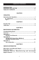
TABLE OF CONTENTS INTRODUCTION .............................................................................i WARNINGS AND CAUTION .........................................................iii TABLE OF CONTENTS .................................................................v CHAPTER I OPERATION Instructions for Operation ...........................................................1 A. Procedures ........................................................................1 Figure 1 ..............................
Operation Chapter I OPERATION: This Chapter discusses the proper steps to safely operate the ODORATOR. Also included are procedures for periodic testing and identification of the ODORATOR’s controls. Operation of the ODORATOR WARNING DURING OPERATION, KEEP THE ODORATOR AWAY FROM OPEN FLAMES. INLET SUPPLY SHOULD NOT EXCEED 4 PSIG AND 1/4 PSIG (7 INCHES WATER COLUMN) IS RECOMMENDED. **NOTE** Connect the ODORATOR to the gas supply with a nonabsorbing, odor-free hose such as high grade urethane, PVC, or Tygon.
Operation 2. Connect the sample hose to the gas supply outlet valve and to the ODORATOR inlet port (1). 3. Open the gas supply outlet valve and the ODORATOR flow metering valve for about 10 seconds to purge the air out of the sample hose. 4. Close the flow metering valve. 5. Turn the ODORATOR “ON”. Raise the exhaust port cover. 6. Wait about 30 seconds and then position the nose about 3/4 inch (20 mm) above the exhaust port and sniff the exhaust. The exhaust must be un-odorized. 7.
Operation 12. If the exhaust does not have a readily detectable odor repeat step 11. If the exhaust does have a readily detectable odor, push and hold the read switch down and record the percent gas in air by volume reading as shown on the LCD. This reading is the readily detectable level which should be noticed by the average person’s sense of smell. 13. Close the gas supply outlet valve, the flow metering valve and then disconnect the sample hose from the gas supply outlet. 14.
Operation ODORATOR 1 2 3 4 5 6 Figure 1 7 8 9 10 Side View 1 1. Gas Inlet 6. Calibration Sticker 2. Power Switch 7. Flow Metering Valve 3. Power Indicator 8. Correction Chart 4. LCD 9. Fine Zero Knob 5. Read Switch 10.
Operation Chapter II Periodic Test: 1. Every thirty (30) days the ODORATOR should be operated with the power switch on and while not hooked up to a gas supply. 2. Wait about 30 seconds and then position the nose about 3/4 inch (20 mm) above the exhaust port and sniff the exhaust. 3. If no odor is detected, turn the ODORATOR “OFF”. The ODORATOR has not absorbed the odorant and is usable. 4.
Maintenance Chapter III MAINTENANCE: Troubleshooting Chart SYMPTOM PROBABLE CAUSE “LO BATT” appears on Weak batteries. LCD. REMEDY Replace batteries. Motor and LCD will not turn on. RMA Speed Indicator “L” comes on. RMA LCD will not zero with Metering valve open or Close metering valve gas supply line attached instrument problem. or RMA. to the ODORATOR. Odorant detected always Contaminated sample hose or flow system Change tubing or RMA. The RMA process may be found on page 18 of this manual.
Maintenance Parts List The following list specifies ODORATOR parts and accessories that are available from the factory or regional office. 0715630 0715631 0711517 22112110 103607-0 0716725 0111004 0716893 Manual, ODORATOR User’s, Methane Correction Chart, Methane Battery, Alkaline “C” size Tubing (available in various lengths), Tygon Label, “Warning” Odorator Regulator, External, Low Pressure, 250 PSI max. Regulator, External, High Pressure, 3000 PSI max.
Appendix A Periodic Test Record Test Date Results Action 8 Operator Name
Appendix A Periodic Test Record Test Date Results Action 9 Operator Name
Appendix B Appendix B ODORATOR Correction Chart for Methane This chart assumes the ODORATOR has been properly zeroed and allowed to run for at least one minute. Methane Correction Chart, 1.00 % Reference ODORATOR % Gas Reading Actual % L.E.L. .10 .20 .30 .40 .50 .60 .70 .80 .90 1.00 Ref. 1.10 1.20 1.30 1.40 1.50 1.4 3.4 5.0 6.6 8.0 10.0 12.4 15.0 17.4 20.0 Ref. 22.0 26.6 31.2 37.2 41.0 10 Actual % Gas 0.08 0.17 0.25 0.33 0.40 0.50 0.62 0.75 0.87 1.00 Ref. 1.10 1.33 1.56 1.81 2.
Appendix C Appendix C ODORATOR Use at Elevation The ODORATOR works by allowing a metered amount of sample gas to mix with a fixed amount of air and the mixture is then tested by a user for odorant detection. The internal components of the ODORATOR are very stable over changes in elevation. The air that is mixed, however, thins out with increasing elevation and must be accounted for. An elevation change of 3000 feet from the calibration can produce reading discrepancies of nearly 10 % which may be corrected.
Appendix C **Note** The elevation correction chart supports new style Methane ODORATORS only. Instruments manufactured before July 1997, that have not been upgraded or calibrated to a methane reference other than 1.00% will not use the elevation correction charts. Consult the factory for using older style ODORATORS at elevation.
Appendix C Elevation Corrections for the Methane ODORATOR The methane ODORATOR mixes air with natural gas to allow the user to determine the percent gas level at which odorant is readily detectable. As elevation is increased or decreased, the air density changes and must be accounted for. Use the Elevation Change Correction Chart as follows: 1. Use the ODORATOR to determine the readily detectable level per the instructions in this manual. 2.
Appendix C The reading as a percentage between the adjacent chart readings can be used to determine the actual value using the same percentage between chart actuals. The reading of .23 is 30% of the difference in the chart higher reading from the chart lower reading. The lower chart reading and actual will be used as the base or reference. .23 - .20 .30 - .20 = .3 or 30% Therefore the actual value will be 30% of the difference in the chart higher actual from the chart lower actual.
Appendix C Therefore the actual value will be 30% of the difference in the chart higher actual from the chart lower actual. Again, the lower value will be the base or reference. 30% of (.22 - .15) = .3 x .07 = .021 which is rounded off to .02 Since the actual value base is .15, the actual value will be .15 + .02 = .17% gas.
.07 .14 .21 .28 .33 .42 .52 .63 .73 .84 .06 .14 .20 .26 .32 .40 16 .49 .60 .69 .80 .88 .76 .66 .54 .44 .35 .29 .22 .15 .07 .92 .80 .69 .57 .46 .37 .30 .23 .16 .07 .96 .83 .72 .59 .48 .38 .32 .24 .16 .08 Down Down Down Down Down 5,000’ 4,000’ 3,000’ 2,000’ 1,000’ .87 .75 .62 .50 .40 .33 .25 .17 .08 A C T U A L 1.03 .90 .78 .64 .52 .41 .34 .26 .18 .08 1.07 .93 .80 .66 .53 .43 .35 .27 .18 .09 1.10 .96 .83 .68 .55 .44 .36 .
Service Chapter IV SERVICE INFORMATION: Warranties and Warranty Repair All instruments and products manufactured by Heath Consultants Incorporated are warranted to be free from defects in material and workmanship for one (1) year from the date of shipment. Furthermore, the warranty on authorized repairs in the Houston Factory Service Center (FSC) and other regions is ninety (90) days materials and thirty (30) days labor. This repair warranty does not extend any other applicable warranties.
Service SERVICE INFORMATION: Return Procedure (RMA): The following steps will expedite the repair of your instrument: 1. Contact Heath Factory Service at 800-432-8487 to request a repair form. The form is available on-line at www.heathus.com - InfoCenter - Repair Forms. 2. Package carefully, using the original shipping carton and cushions if available and return all components including the repair form.
Service SALES, CUSTOMER SERVICE, AND INSTRUMENT REPAIR National Toll Free # 1-800-HEATH-US (1-800-432-8487) REGIONAL SALES, CUSTOMER SERVICE, AND INSTRUMENT REPAIR Eastern Region Heath Consultants Incorporated 575 Park Way Monongahela, PA 15063 Phone: 724-242-3145 Fax: 724-872-3206 Southwest Region Heath Consultants Incorporated 9030 Monroe Road Houston, TX 77061 Phone: 713-844-1300 Fax: 713-844-1309 Western Region Heath Consultants Incorporated 30 Main Avenue, Unit 3 Sacramento, CA 95838 Phone: 916-921-519
Service NOTES 20
Service NOTES 21
Heath Consultants Incorporated operates under a continual product improvement program and reserves the right to make improvements and/or changes without prior notification. Heath Consultants Incorporated Houston, TX 713-844-1300 Fax: 713-844-1309 1-800-HEATH-US www.heathus.com Heath...