
Manual


8
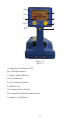
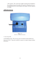
Controls
The Sure-Lock low frequency transmitters have several controls and indicators
with which the operator must become familiar (Figure 1-2).
A. LED INDICATOR. Indicates the transmitter’s output level and battery
charge level via the LED’s relative brightness.
B. POWER TEST SWITCH. Pressing and holding this switch down will al-
low the use of the LED Indicator for testing the transmitter.
C. POWER ON-OFF SWITCH. Used to turn the transmitter power on and off.
D. DIRECT ACCESSORY (81K OUTPUT) JACK. Used for connecting the
81K output to the target conductor.
E. CONDUCTOR DIRECTION ARROW. The transmitter, when used induc-
tively, must be placed with the conductor direction arrow directly over and
parallel to the target conductor.