
Full Product Manual
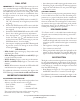

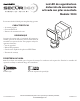

4 To see operational and troubleshooting information and videos,
go to www.hzsupport.com
210449-01
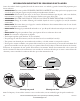
Figure 8
Figure 5
Figure 6
Figure 7
R
E
S
E
T
/ 0 +
217,0(
6HQVLWLYLW\
(FR3RZHU0RGH
2Q 2II
6
7HVW
2II
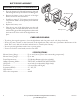
FINAL ASSEMBLY
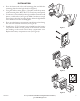
Slide the rear of the light xture down onto the mounting plate until
it snaps into place (see Figure5).
IMPORTANT:
• If wall mounted, make sure the xture is mounted with the sensor
below the lamp head (see page 2).
• If eave mounted, mount the xture with sensor facing away from
the house wall (see page 2). Rotate the sensor so the controls on
the bottom of the sensor (see Figure 7) face the ground.
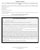
TESTING AND ADJUSTMENTS
R
E
S
E
T
/ 0 +
217,0(
6HQVLWLYLW\
(FR3RZHU0RGH
2Q2II
6
7HVW
2II
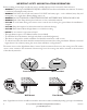
CAUTION: To avoid water damage, motion sensor con-
trols must be facing the ground when installation is complete.
1. Slide the sensitivity (SENS) switch to the “L” position, the
ON-TIME switch to the TEST position, and the ECO POWER
MODE switch to the OFF position (see Figure 7).
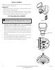
2. Walk through the coverage area noting where you are when the
lights turn on. Also, the LED indicator behind the motion sen-
sor lens will glow blue when motion is detected (see Figure 8).
Note: e blue LED will turn o 30 seconds after all motion has
stopped.
3. If needed, gently grasp the motion sensor and move it from side
to side or up and down to adjust the detection zone.
4. If needed, gently grasp the lamp head and move it from side to
side or up and down to adjust the light coverage area.
LED Indicator