
Installation Sheet


TRANSFORMER INSTALLATION INSTRUCTIONS
IMPORTANT: READ ALL INSTRUCTIONS BEFORE INSTALLING TRANSFORMER.
FOLLOW ALL NATIONAL AND LOCAL ELECTRICAL CODES.
CONTACT A QUALIFIED ELECTRICIAN IF THERE ARE ANY QUESTIONS AS TO THE SUITABILITY OF THE SYSTEM.
1. WARNING: TURN OFF POWER AT FUSE OR CIRCUIT BREAKER BEFORE INSTALLING TRANSFORMER.
2. Locate or install a junction box close to the selected mounting location for your chime. Do not install transformer in an
attic location. For new installation remove cover plate and knockout from junction box.
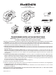
3. Mounting locknut type transformer (Model 122): From exterior of junction box, pass transformer wires through hole
in junction box. To secure transformer to junction box, fasten locknut to transformer’s threaded shaft on inside of junction
box (see Figure 1).
Mounting clamp type transformer (Model 125): Note: Mounting clamp requires a junction box with flat sides and
knockouts. From exterior of junction box, pass transformer wires through knockout hole in junction box. Insert transformer
clamp through same knockout hole as wires. Tighten screw (provided) against edge of knockout hole on junction box
(see Figure 2).
4. Connecting Transformer Wires to Power Wires: If necessary, strip 1/2” of insulation from power supply wires (see
Figure 3). Twist black wire lead from transformer to black wire lead from power supply. Twist white wire lead from trans-
former to white wire lead from power supply. Twist green ground wire from transformer to bare (or green insulated)
copper lead of power supply. For metal junction boxes, it is required to connect green ground wire from transformer to
the metal junction box or clamp it to the metal conduit.
Insulate each connection using UL Approved wire nut (see Figure 4).
5. Check all connections and replace cover plate.
6. Attach low voltage wires from chime, bell, or buzzer to secondary screw terminals on transformer (see wiring diagram
included with the chime, bell, or buzzer) (see Figure 5).
For Model 125 Only: See arrow markings on transformer to determine correct screw terminals for 8, 16, or 24 volt
connection (see Figure 6).
TO REPLACE EXISTING TRANSFORMER, FOLLOW INSTRUCTIONS ABOVE (OMIT STEP 2). LABEL WIRES PRIOR
TO REMOVAL OF EXISTING TRANSFORMER.
P.O. Box 90045
Bowling Green, KY 42102-9045
Figure / Figura 1 Figure / Figura 2
Figure / Figura 6Figure / Figura 5
1/2"
Figure / Figura 3
Figure / Figura 4
© 2016 HeathCo LLC 208431-03
8V 10VA 16V 10VA
24V 20VA
LOAD
8V 10VA 16V 10VA 24V 20VA
8V 10VA 16V 10VA
24V 20VA
LOAD
8V 10VA 16V 10VA
24V 20VA
LOAD