
User's Manual


3
598-1116-00
DRAFT COPY
INDOOR/OUTDOOR
SCREW-IN LIGHT
RECEIVER
Features and Ratings:
• Up to 150 Watt incandescent load.
• No wiring required.
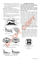
1. Screw module into light socket.
2. Screw incandescent bulb up to rated watt-
age into module.
Caution: Do not exceed the maximum load
limits listed above.
3. Check operation. Either activate remote
motion sensor or toggle ON/OFF switches
on remote control to check operation.
REMOTE MOTION
SENSOR
Features:
• No wiring required.
• Up to 70 feet sensing range, 180° Coverage.
• Adjustable sensitivity.
• Day/Night or Night only operation.
• Test mode.
• Uses 2 AA batteries.
• Wall or eave mount.
Select Night or 24 Hour Mode
This sensor is able to detect motion day and night
or night only. To set the detection mode, remove
rear panel by sliding the panel down. Remove
batteries if necessary. Slide the DETECT switch
to either the DAY/NIGHT or NIGHT ONLY posi-
tion. Replace rear panel by reversing the above
instructions.
Installing Batteries
Before mounting sensor, remove rear panel by
sliding the panel down. Install 2 AA batteries
according to polarity markings inside the battery
compartment. Replace rear panel by reversing the
above instructions.
Battery Compartment - Rear View
DETECT
CODES
1234
DAY
NIGHT
NIGHT
ONL
Y
Detect
Control
Installing Remote Sensor
1. Install sensor mounting bracket where mo-
tion detection is desired. Attach sensor
mounting bracket to a sturdy object (i.e.
tree, post, house, etc.) using two screws
provided. Make sure unit has an unob-
structed view.
2. Install remote sensor to mounting bracket.
Using a Philips-head screwdriver, loosen the
clamp screw on the mounting bracket. Insert
swivel ball mount on sensor into mounting
bracket socket (
Note:
You should hear a
snap). Aim sensor toward area where detec-
tion is desired. Tighten clamp screw.
IMPORTANT:
The sensor must be mounted with
the bottom cover facing down in order to maintain
water tightness.
Check Operation and Adjustment
The RANGE control and ON-TIME control are
located on the bottom of the sensor. Using your
fingernails or a small, flat-head screwdriver, gen-
tly pry the cover until it opens.
1. Check Operation. Set the ON-TIME control
to TEST mode. Walk in front of sensor unit.
The LED indicator light located on the bot-
tom of the sensor should flash when motion
is detected.
2. Adjust Sensor. Turn the RANGE control to
the mid position and ON-TIME control to the
TEST position. Walk through coverage area
noting where you are when the LED begins
to flash. Loosen the clamp screw and move
the sensor to change the coverage area.
Tighten clamp screw when finished. Do not
overtighten clamp screw.
3. Adjust Range Control. To increase sensitiv-
ity, turn the RANGE control toward MAX. To
decrease sensitivity, turn the RANGE con-
trol toward MIN.
Note:
If the RANGE is set
too high, false triggering may result in some
environments.
Installing Remote Sensor
Mounting Bracket
Clamp
Screw
Nut
Sensor
Mounting Screw
Swivel Ball Mount
Mounting
Bracket
Socket