Owner’s Manual Installation and Operation CONSTITUTION EPA CERTIFIED WOODBURNING FIREPLACE Tested and Listed by Model: O-T L C Portland Oregon USA US OMNI-Test Laboratories, Inc. C40 CAUTION DO NOT DISCARD THIS MANUAL • Important operating and maintenance instructions included. • Read, understand and follow these instructions for safe installation and operation.
Read this manual before installing or operating this appliance. Please retain this owner’s manual for future references. Congratulations Congratulations on selecting a Heatilator wood burning fireplace. The Heatilator fireplace you have selected is designed to provide the utmost in safety, reliability, and efficiency. This Owner's Manual should be retained for future reference. We suggest that you keep it with your other important documents and product manuals.
Safety Alert Key: • • • • DANGER! Indicates a hazardous situation which, if not avoided will result in death or serious injury. WARNING! Indicates a hazardous situation which, if not avoided could result in death or serious injury. CAUTION! Indicates a hazardous situation which, if not avoided, could result in minor or moderate injury. NOTICE: Indicates practices which may cause damage to the fireplace or to property.
Hearth & Home Technologies Inc. LIMITED LIFETIME WARRANTY Hearth & Home Technologies Inc., on behalf of its hearth brands (”HHT”), extends the following warranty for HHT gas, wood, pellet, coal and electric hearth appliances that are purchased from an HHT authorized dealer.
WARRANTY CONDITIONS: • • • • This warranty only covers HHT appliances that are purchased through an HHT authorized dealer or distributor. A list of HHT authorized dealers is available on the HHT branded websites. This warranty is only valid while the HHT appliance remains at the site of original installation. Contact your installing dealer for warranty service. If the installing dealer is unable to provide necessary parts, contact the nearest HHT authorized dealer or supplier.
1 Listing and Code Approvals A. Appliance Certification This fireplace system has been tested and listed in accordance with UL127 and ULC-S610-M87 and (UM) 84-HUD standards, and has been listed by OMNI Test Laboratory Inc., for installation and operation in the United States and Canada as described in this manual. This fireplace has been tested and listed for use with the SL300 Series chimney (with the CAK4A Air Kit) and fireplace components listed in Section 12.
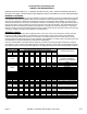
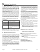
C. BTU & Efficiency Specifications EPA Certified: 3.25 grams per hour Efficiency: up to 77.8% BTU Output with EPA test fuel: with cord wood: 51,400/ hr. 70,000/hr Vent Size: 8 inches Firebox Size: 2.7 cubic feet Max Wood Length: 24 inches Fuel: Cord Wood Shipping Weight: 650 lbs Notice: This fireplace is tested and approved as a decorative fireplace. It should not be factored as a primary heat source in residential heating calculations. D.
2 User Guide Operating Instructions WARNING HOT SURFACES! Glass and other surfaces are hot during operation AND cool down. Hot glass will cause burns. • DO NOT touch glass until it is cooled • NEVER allow children to touch glass • Keep children away • CAREFULLY SUPERVISE children in same room as fireplace. • Alert children and adults to hazards of high temperatures. High temperatures may ignite clothing or other flammable materials.
INCORRECT POSITIONS B. General Information Fireplaces, as well as other woodburning appliances, have been used safely for many years. It has been our experience that most problems are caused by improper installation and operation of the fireplace. Make certain that installation and operation of the fireplace system is in accordance with these instructions. It is extremely important that the fire be supervised whenever the fireplace is in use.
E. Wood Fuel Moisture content Hardwood vs. Softwood Your fireplace’s performance depends a great deal on the quality of the firewood you use. Contrary to popular belief, one species of wood varies very little to the other in terms of energy content. All seasoned wood, regardless of species, contains about 8,000 BTU’s per pound. The important factor is that hardwoods have a greater density than softwoods. Therefore, a piece of hardwood will contain about 60% more BTU’s than an equal size piece of softwood.
Seasoned Wood • Cut logs to size • Split to 6 in. (152 mm) or less • Air dry to a moisture content of around 20% - Soft wood - about nine months - Hard wood - about eighteen months Notice: Seasoning time may vary depending on drying conditions. Storing Wood Splitting wood before it is stored reduces drying time. The following guideline will ensure properly seasoned wood: • Stack the wood to allow air to circulate freely around and through the woodpile.
OPEN CLOSE Outside Air Control Handle Figure 2.4 General Outside Air operating parts G. Clear Space Near the Fireplace Combustible materials must not be stored on the hearth extension. Room furnishings such as drapes, curtains, chairs or other combustibles must be at least 4 ft (1219mm) from the open front of the fireplace. H. Glass Doors This fireplace has been tested and listed for use with doors as specified in Section 12.
2. What To Do if Your Stove is Over-Firing J. Fire Safety To provide reasonable fire safety, the following should be given serious consideration: 1. Install at least one smoke detector on each floor of your home to ensure your safety. They should be located away from the heating appliance and close to the sleeping areas. Follow the smoke detector manufacturer’s placement and installation instructions, and be sure to maintain regularly. 2.
M. Starting a Fire Before lighting your first fire in the fireplace, make certain that the baffle and the ceramic blanket are correctly positioned. It should be resting against the rear support. Also refer to care and cleaning of plated surfaces on Section 5 before lighting your first fire. NOTICE: Fireplace should be run full open for a minimum of 30 minutes a day during heating season to keep air passages clean.
Final stage: The final stage of burning is the charcoal stage. This occurs when the flammable gases have been mostly burned and only charcoal remains. This is a naturally clean portion of the burn. The coals burn with hot blue flames. It is very important to reload your fireplace while enough lively hot coals remain in order to provide the amount of heat needed to dry and rekindle the next load of wood. It is best to open the air control for a short while before reloading. This livens up the coalbed.
P. Manual Timer Override R. Burn Rates If timer is unintentionally engaged, push the Timer Override Lever to the left. This will disengage the timer and set the Fireplace back to the low setting. Figure 2.6 HIGH - Maximum Heat: Fully open (Combustin Air Control all the way to the right). It is important to do this when reloading the fireplace. Failure to do this could result in excessive emissions (smoke).
3 Troubleshooting This fireplace will operate correctly only if adequate ventilation is provided to allow proper draft to the fireplace system. Hearth & Home Technologies assumes no responsibility for the improper performance of the fireplace system caused by inadequate draft due to environmental conditions, down drafts, tight sealing construction of the structure, or mechanical exhausting devices which will create a negative air pressure within the structure where the fireplace is located. A.
nd ti ina y term e n m i h c ? on Bird's nest or leaves in termination cap? ds ar ou Overhanging tree? n wi g n o Str Structural changes in chimney area? Another appliance in home also exhausting air (furnace, fan, Unsealed dryer, etc.)? can lights? Overhead fan operating? Creosote buildup in flue? Air register from furnace near fireplace? Doors opening and closing? Window closed for start-up? Figure 3.
C. Diagnostics and Problem Solving 1.
4. I don’t get enough/any heat.
4 Maintenance and Servicing the Fireplace A. General Maintenance 1. Creosote (Chimney) Cleaning • Frequency: As necessary; at least annually before lighting stove or once every 2 months during heating season. Formation and Need For Removal: When wood is burned slowly, it produces tar and other organic vapors which combine with expelled moisture to form creosote. The creosote vapors condense in the relatively cool chimney flue of a newlystarted or a slow-burning fire.
4. Care and Cleaning of Plated Surfaces 2. Disposal of Ashes Frequency: As necessary By: Homeowner Task: See the following instructions. • • Ashes should be placed in a metal container with a tight fitting lid. The closed container of ashes should be placed on a non-combustible floor or on the ground, well away from all combustible materials, pending final disposal.
6. Maintenance Task List Inspect Screens Maintenance Tasks 1. Assess condition of screen and replace as necessary. 2. Verify maintenance of proper clearance to combustible household objects. Glass Doors 1. Inspect glass panels for cracks. Replace if this condition is present. 2. Confirm there is no damage to glass or glass frame. Replace as necessary. 3. Inspect door rope. Confirm glass does not move around in glass frame 4. Clean glass using a non-abrasive cleaner. Door Rope (Dollar Bill Test) 1.
2. Firebrick Replacement The firebox of your fireplace is lined with high quality firebrick, which has exceptional insulating properties. There is no need to use a grate; simply build a fire on the firebox floor. Do not operate the fireplace without bricks. Lay bottom bricks in unit. 3. Install rear bricks on the top of the bottom bricks. Slide top of bricks under clip on back of firebox wall and push bottom of brick back. 4.
3. Baffle Removal and Installation 1. Remove all ash from firebox, and extinguish all hot embers before disposal into a metal container. 2. Remove the baffle protection channel by turning it down and pulling it out of the firebox. See Figure 4.5 Figure 4.7 Removing Baffle (shown without ceramic blanket) 4. Fan Replacement Figure 4.5 Removing Baffle Protection Channel 3. Remove ceramic blanket from above the baffle. 4. With a 3/16 in.
Fan Replacement Instructions 1. Remove the brick from the bottom of the fireplace and 3 of the back vertical bricks. 2. Remove the 2 screws from the access panel in the firebox floor. See Figure 4.8. 3. Pry up the access panel using the screwdriver slot and completely remove the panel. Removing the fan 1. Unplug the wire harness. 2. Lift fan from locating pins and remove. Repeat for second fan if necessary. See Figure 4.9. 3. Connect new fan wires to wire harness. 4.
5. Timer Assembly Replacement CAUTION Shock Risk! Disconnect power by turning off circuit breaker BEFORE servicing. Black Knob Remove 2 screws in cover plate Spring Handle Cover Plate Figure 4.13 Linkage Arm 1/4” bolts Mechanical Timer Cov er P Timer Assemby late Figure 4.11 Timer Assembly 1. Remove both doors by lifting doors up and off of hinges. 2. Remove the black knob and spring handle. 3. Remove the outside air knob and then the 4 screws from each corner of fascia and remove the fascia.
7. Move slider control rod and linkage arm to the right and out of the way. Pull rod down and out towards you. Lay the control arm down. Figures 4.16 and 4.17. 8. The timer assembly is bolted under the face. Use a 7/16 socket wrench to remove the 2 bolts. Figure 4.18. 9. There is very little room to pull the timer assembly out the front of the fireplace. Place your hand through the access door in the floor of the fireplace. Let the timer assembly drop down and then rotate it up through the access door.
5 5 4 4 3 2 1 3 D cut side of timer shaft must face away from the Linkage Timer Arm 10 7 8 9 6 Figure 4.21 Figure 4.23 Exploded View of Entire Assembly for Point of Reference only 3. Place linkage control arm over timer shaft and tighten set screw. Figure 4.22.
C.
5 Getting Started Installer Guide A.
B. Design and Installation Considerations D. Negative Pressure Notice: Check building codes prior to installation. Warning! Risk of Asphyxiation! Negative pressure can cause spillage of combustion fumes and soot. Fire must draft properly for safe operation. • • Installation MUST comply with local, regional, state and national codes and regulations.
E. Locating Fireplace & Chimney Location of the fireplace and chimney will affect performance. • • • • • • Install within the warm airspace enclosed by the building envelope. This helps to produce more draft, especially during lighting and die-down of the fire. Penetrate the highest part of the roof. This minimizes the effects of wind loading. Locate termination cap away from trees, adjacent structures, uneven roof lines and other obstructions. Minimize the use of chimney offsets.
F. Tools and Supplies Needed Before beginning the installation be sure the following tools and building supplies are available: Reciprocating saw Framing material Pliers Non-combustible sealant Hammer Gloves Phillips screwdriver Framing square Flat blade screwdriver Electric drill and bits Plumb line Safety glasses Level Tape measure 1/2-3/4 in. length, #6 or #8 self-drilling screws Misc. screws and nails G.
6 Framing & Clearances A. Selecting Fireplace Locations Several options are available to you when choosing a location for your fireplace. This fireplace may be used as a room divider, installed along a wall, across a corner or used in an exterior chase. See Figure 6.1 NOTICE: • Illustrations and photos reflect typical installations and are FOR DESIGN PURPOSES ONLY. • Illustrations/diagrams are not drawn to scale. • Actual installation/appearance may vary due to individual design preference.
B. Clearances Warning! Risk of Fire! You must comply with all minimum air space clearances to combustibles as specified in Figure 6.2. Do NOT pack required air spaces with insulation or other materials.Framing or finishing material used on the front of, or in front of, the appliance closer than the minimums listed.must be constucted entirely of non-combustible materials (i.e., steel studs, concrete boaed, etc.). Failure to comply may cause fire. Storm Collar of) (ro Roof Flashing 2 in. (51 mm) min.
1. MINIMUM CLEARANCES TO COMBUSTIBLES WITHIN ENCLOSURE AREA: Appliance to backwall Appliance to sidewall Duct boots to framing Top standoffs to header Door opening to sidewall 1 in. (25 mm) 1 in. (25 mm) 0 in. (0 mm) 0 in. (0 mm) 22-7/8 in. (581 mm) EXPOSED SURFACES Faceplate to sidewall Heat zone air grills to ceiling 16 in. (406 mm) 12 in. (305 mm) MANTEL Combustible and non-combustible mantel minimum height from base of fireplace to underside of mantel 60 in.
D. Electrical Access and Wiring Diagram WARNING! Fire Risk! Do not apply combustible finishing materials over any part of the front of this fireplace. NOTICE: The manual override switch, rheostat speed control and cover plate are supplied. You will need to supply: 14-3 wire with ground; 14-2 wire with ground; standard wall mount junction box; wire nuts. • • 1. Remove junction box cover plate on the bottom right side of the fireplace.
7 Installation of Fireplace Caution! Risk of Cuts/Abrasions. Wear protective gloves and safety glasses during installation. Sheet metal edges are sharp. A. Install the Outside Air Kit This fireplace will operate correctly only if adequate ventilation is provided to allow proper draft to the fireplace system. See Section 6. An outside air kit must be used for combustion to minimize the effects of negative pressure within the structure.
Attic insulation shield must be used to keep insulation away from chimney. 3 ft min. from top of uppermost chimney section to air inlet. Ceiling firestop on floor of attic. Fiqure 7.2 Outside Air Inlet Locations Open/Close Knob for outside air OPEN CLOSE Termination Cap supplied with fireplace 6 in. (152mm) metal flex or rigid pipe Figure 7.
B. Secure the Fireplace • Position the Fireplace This fireplace may be placed on either a combustible or noncombustible continuous flat surface. Follow the instructions for framing in Section 6.C. Slide the fireplace into position. Be sure to provide the minimum 1 in. air clearance at the sides and at back of the fireplace assembly. See Section 6.B. Caution! Risk of Cuts/Abrasions. Wear protective gloves and safety glasses during installation. Sheet metal edges are sharp.
8 Chimney Assembly Notice: Chimney performance may vary. • Trees, buildings, roof lines and wind conditions affect performance. • Chimney height may need adjustment if smoking or overdraft occurs.
A. Chimney Requirements NOTICE: You must provide support for the pipe during construction and check to be sure inadvertent loading has not dislodged the chimney section from the fireplace or at any chimney joint. Vertical distances are measured from the base of the fireplace as shown in Figure 8.2 Minimum overall straight height 13 ft 3.96 m 14.5 ft 4.42 m Double offset/return minimum height 20 ft 6.1 m Maximum height 50 ft 15.24 m Maximum chimney length between an offset and return 20 ft 6.
C. Using Offsets/ Returns • • Use an offset/return to bypass overhead obstructions. An offset and return can be used as a single entity or separated by chimney section(s). Warning! Risk of Fire! Do not use offset/returns greater than 30°. Chimney draft will be restricted and could cause overheating and fire. Secure offsets vwith screws ( not to exceed 1/2” / 13 mm in length) Secure returns with strapping. Straight chimney sections may be secured with screws.
D. Assemble the Chimney Sections Use only those components described in this manual. Substitute or damaged chimney components could impair safe operation and cause overheating and fire. Warning! Risk of Fire! Do NOT install substitute or damaged chimney components. Attach either a straight chimney section or an offset to the top of the fireplace (depending on your installation requirement).
ROOM ABOVE (non-insulated ceiling) Wire Ties B 4" Flex Wire Ties Figure 8.6 • • • • • 2 in. (51mm) clearance ATTIC ABOVE (insulated ceiling) Ceiling firestop attached to top of framing Caution! Risk of Fire! Ceiling firestops must be used whenever the chimney penetrates a ceiling/floor. • Ceilng firestop attached to bottom of framing Installing Flex Pipe F. Install Ceiling Firestops • A Chase construction requires ceiling firestops at each floor or every 10 ft (3.05 m) of clear space.
G. Install Attic Insulation Shield Warning! Risk of Fire! You MUST install an attic insulation shield when there is any possibility of insulation or other combustible material coming into contact with the chimney. • Do NOT pack insulation between the chimney and the attic insulation shield. • Failure to keep insulation and other materials away from chimney pipe could cause fire. • Do NOT offset chimney inside insulation shield. Bend remaining tabs to rest against pipe to prevent insulation from falling in.
WARNING! Risk of Fire! Secure offsets with screws (not to exceed 1/2in./13mm in length). Secure returns with strapping. Straight chinney sections may be secured with screw (not to exceed 1/2in./13mm in length) at the joints Keep chimney sections from separating or twisting. Straps I. Double-check the Chimney Assembly Continue assembling the chimney sections up through the ceiling firestops as needed. While doing so, be aware of the height and unsupported chimney length limitations given under Section 8.A.
M. Chimney Termination Requirements • • • • • Install a cap approved and listed for this fireplace system. Locate cap where it will not become plugged by snow or other materials. Locate cap away from trees or other structures. The bottom of the termination cap must be at least 3 ft (.91 m) above the roof AND at least 2 ft (.61 m) above any portion of roof within 10 ft (3.05 m) as shown in Figure 8.13 The distance required between caps is shown in Figure 8.13. Slanted Roofs Chimney must extend 2 ft (.
N. SL-300 Series Ceiling/Roof Thimble NOTICE: REQUIRED for manufactured homes. CHIMNEY FLASHING THIMBLE EXTENSION 1. Locate the point where the chimney will exit the roof by plumbing down to the center of the chimney. Lay out, cut and frame a 14-1/2 in. (368 mm) square opening (measured on the horizontal) through the ceiling and roof structure. Consult local codes for framing details. 2. The thimble must extend completely through the roof structure shielding combustible materials.
9 Chase Installations A. Construct the Chase A chase is a vertical boxlike structure built to enclose the fireplace and/or its vent system. Vertical chimneys that run on the outside of a building must be installed inside a chase. Three examples of chase applications are shown in Figure 9.2 In cold climates, it is recommended that the chase insulated using batt type insulation between the joists. Construction of the chase may vary with the type of building.
B. Install Fireplace & Chimney • TR344 Round Termination Cap Termination Cap Install as per Sections 7 and 8. Slip storm collar around chimney pipe before termination cap pipe is snapped into the chimney pipe. C. Install Chase Top • • • • • You MUST use a chase top in a chase installation. Chase tops are available from your Heatilator dealer or may be field constructed. Include a turndown and drip edge to prevent water from seeping into the chase. Include a 2 in.
• ST375 Square Termination Cap • Place waterproof caulk or sealer under each flange of the termination cap and on top of each screw to help prevent leaks. Flange Termination Cap Collar 2 in. (51 mm) Minimum Height The last section of pipe must stop between 2 in. (51 mm) above the top of the chase and 4 3/4 in. (121 mm) below the top of the chase. Chase Top TCT375 Terra Cotta Cap Place waterproof sealer under each flange of the termination cap and on top of each screw to help prevent leaks.
10 Finishing A. Non-Combustible Materials • • Materials which will not ignite and burn, composed of any combination of the following: - Steel - Iron - Brick - Tile - Concrete - Slate - Glass - Plasters Materials reported as passing ASTM E 136, Standard Test Method for Behavior of Metals, in a Vertical Tube Furnace at 750° C C. Non-Combustible Facing Material Installation WARNING! Risk of Fire! Follow these instructions exactly. Facing materials must be installed properly to prevent fire.
• Non-Combustible Sealant Material Sealants which will not ignite and burn: Super Calstick 1in. (25mm) OVERLAP Metal strips 2 in. (51mm) under edge of Fireplace and Hearth Extension and 2 in. (51mm) on both side of fireplace opening. Nail or screw metal strips in place. Figure 10.
Warning! Fire Risk! Hearth extensions are to be installed only as illustrated to prevent high tempertures from occurring on concealed combustible materials. A B Model # Constitution A in. mm B 41 20 1041 508 Figure 10.5 Hearth Extension Dimension 1. Position the Hearth Extension Position and secure the hearth extension over the protective metal strips that have been placed partially under the fireplace front. These strips should be protruding approximately 2 in.
Fascia Outer Can Flange ........... Tile or Marble Combustible Floor Minimum 20 in. (508mm) in front and 8 in. (203mm) on sides to fuel loading doors ....................................... ....................................... Tile or Marble Ember Strip (Seal gap with High temp, noncombustible Minimum 4 in. (101.6 mm) Cement Board or equivalent, (or two 1/2 in. pieces) sealant able to withstand and "k" value = 0.49. Micore 300 300°) Figure 10.9 Fireplace and Hearth Extension Flush on the Floor.
F. Mantel A combustible mantel may be positioned no lower than 60 in. (1524mm) from the base of the fireplace. The combustible mantel may have a maximum depth of 12 in. (305mm). Combustible trim pieces that project no more than 3/4 in. (19mm) from the face of the fireplace can be placed no closer than 6 in. (152mm) from the side of the decorative front. See Figure 10.
11 Accessories DUCT RUN REQUIREMENTS A. Heat Zone Kit (Optional) This kit is tested and safe when installed in accordance with this installation manual. It is your responsibility to read all instructions before starting installation and to follow these instructions carefully during installations. MAXIMUM Duct Run = 40-ft. (12m) MINIMUM Duct Run = 36 in. (914mm) DUCTING MATERIAL Installation of this kit MUST by performed by a qualified service technician. 6 in.
INSTALLATION 1. Remove the knockout or cover plate from the top of the fireplace and discard it. See Figure 11.2. 2. Cut a 3 in. (76mm) hole in the insulation board as per the dimensions shown in Figure 11.2 3-13/16 in. (97mm) 3-1/8 in. (79mm) Adapter CL Mounting Plate Figure 11.4 Starter Pipe 5. Slide the starter pipe into the fireplace, matching the holes in the plate to the holes in the fireplace. Knockout ole m) h (76m 3 in. board a t u n C ulatio in ins Figure 11.2 6.
NOTICE: Secure the duct so that clearance to the fireplace outer wrap is maintained. Tape all seams with aluminum tape 1-1/4 in. (32mm) minimum width or as specified by local codes.) 2 x 4 Wall Fan Housing 9. Seal all the way around the inside of the Return Air Grille to prevent hot air being drawn back into the venting system using gasketing supplied with the kit. Leave 1/4 in. (6mm) clearance from all 4 outer edges. Trim excess gasketing. See Figure 11.
B. Firescreen A firescreen must be used to control sparks if the homeowner choses to operate the fireplace with the doors open; and it must remain in place whenever the fireplace will be operating in this manner. Glass doors or firescreens must not be used to hold burning material inside the fireplace. Only those glass doors specifically tested and listed for use with the specific fireplace model should be used. Use both hands to stabilize the screen. Ensure that the screen is fully attached.
12 Reference Materials A. Fireplace Dimensions FRONT VIEW SIDE VIEW A F J B E G I H D Fan Electrical Access (right side of fireplace) C TOP VIEW K L Constitution A B C D E F in 3-1/2 31-1/8 40 37 40-5/16 43-13/16 mm 89 791 1016 940 1024 1100 G H I J K L in. 6-1/2 9-11/16 5-7/8 1 23-1/8 11-1/8 mm 165 246 149 25 587 283 Figure 12.
B. Chimney Components The following drawings show the SL-300 Series chimney and fireplace components which may be safely used with this fireplace. Catalog No. Description Catalog No. Description CAK4A Chimney Air Kit RF371 Roof Flashing - 6/12 to 12/12 Pitch ID4 Insulated Duct / Outside Air TR344 Round Termination Cap UD4 Uninsulated Duct / Outside Air TR342 Round Telescoping Termination Cap SL306 Chimney Section - 6 in.
10-1/2 in. (267 mm) (527 mm) 24 in. 2 in. 20-3/4 in. (610 mm) (51 mm) Inside Diameter 8 in. 10-1/2 in. (267 mm) (203 mm) Outside Diameter 10-1/2 in. AS8 Straight Attic Insulation Shield JB877 Joint Band CB876 Chimney Bracket (267mm) SL3 - Chimney Stabilizer 24-5/8 in. (625 mm) 29 in. (737 mm) 12966A Manufactured Home Thimble Inside Diameter 8 in. 16-5/8 in. 16-5/8 in. (422 mm) (422 mm) 72 in. (203 mm) (1829 mm) Outside Diameter 10-1/2 in. 36 in. (914 mm) 10-7/8 in.
B B A A C C DTS134/DTS146 DTO134 DTO146 DTS134 DTS146 Page 66 DTO134/DTO146 Decorative Caps in mm A 34 864 B 20 508 C 24 610 in mm 46 1168 22.7 576 26 660 in mm A 34 864 B 21.18 538 C 24 610 in mm 46 1168 21.
C40 Beginning Manufacturing Date: June 2003 Ending Manufacturing Date: Active C. Service Parts Constitution Woodburning Fireplace 1 2 3 11 10 4 8 5 6 9 7 13 12 15 14 Part number list on following page.
C40 Beginning Manufacturing Date: June 2003 Ending Manufacturing Date: Active Service Parts IMPORTANT: THIS IS DATED INFORMATION. When requesting service or replacement parts for your appliance please provide model number and serial number. All parts listed in this manual may be ordered from an authorized dealer. ITEM DESCRIPTION COMMENTS PART NUMBER 1 8 in. Starter Section SL1 2 Blanket, Kaowool 832-3401 Stocked at Depot Y #3 Brick Set 3.2 3 3.1 3.1 3.1 3.2 3.3 3.3 3.3 3.3 3.3 3.
C40 Beginning Manufacturing Date: June 2003 Ending Manufacturing Date: Active Service Parts IMPORTANT: THIS IS DATED INFORMATION. When requesting service or replacement parts for your appliance please provide model number and serial number. All parts listed in this manual may be ordered from an authorized dealer.
This page intentionally left blank.
D. Contact Information Heatilator, a brand of Hearth & Home Technologies Inc. 1915 W. Saunders St. Mt. Pleasant, IA 52641 www.heatilator.com Please contact your Heatilator dealer with any questions or concerns. For the location of your nearest Heatilator dealer, please visit www.heatilator.com.