Owner’s Manual Installation and Operation Models: GB4336, GB4336L, GB4336I, GB4336IL, GB4942, GB4942L, GB4942I, GB4942IL B-Vent Gas Appliance CAUTION WARNING WARNING If the information in these instructions is not followed exactly, a fire may result causing property damage, personal injury, or death. • Do not store or use gasoline or other flammable vapors and liquids in the vicinity of this or any other appliance. HOT! DO NOT TOUCH. SEVERE BURNS MAY RESULT. CLOTHING IGNITION MAY RESULT.
Read this manual before installing or operating this appliance. Please retain this owner’s manual for future reference. Congratulations Congratulations on selecting a Heatilator gas appliance—an elegant and clean alternative to wood burning appliances. The Heatilator gas appliance you have selected is designed to provide the utmost in safety, reliability, and efficiency. As the owner of a new appliance, you’ll want to read and carefully follow all of the instructions contained in this owner’s manual.
Table of Contents 1 Listing and Code Approvals A. B. C. D. E. F. 4 Appliance Certification . . . . . . . . . . . . . . . . . . . . . . . . . 4 Glass Specifications . . . . . . . . . . . . . . . . . . . . . . . . . . 4 BTU Specifications . . . . . . . . . . . . . . . . . . . . . . . . . . . 4 High Altitude Installations . . . . . . . . . . . . . . . . . . . . . . 4 Non-Combustible Materials . . . . . . . . . . . . . . . . . . . . . 4 Combustible Materials . . . . . . . . . . . . . . . . . . . . . . . . .
1 Listing and Code Approvals A. Appliance Certification MODELS: GB4336/GB4942 Series LABORATORY: Underwriters Laboratories, Inc. (UL) TYPE: B-Vent Gas Appliance STANDARD: ANSI Z21.50-2000/CSA 2.33-2000, IR41, P4 and IR55 This product is listed to ANSI standards for “Vented Gas Fireplaces” and “Gas Fired Appliances for Use at High Altitudes”.
2 Getting Started A. Design and Installation Considerations Heatilator B-vent gas appliances are designed to operate with all exhaust gases expelled to the outside of the building, and combustion air pulled from the room. CAUTION Check building codes prior to installation. • Installation MUST comply with local, regional, state and national codes and regulations.
To minimize the effects of negative air pressure, the following must be considered: B. Negative Pressure • WARNING Asphyxiation Risk • Negative pressure can cause spillage of combustion fumes and soot. • Fire needs to draft properly for safe operation. • • • Draft is the pressure difference needed to vent fireplaces successfully. Considerations for successful draft include: • • • Preventing negative pressure. Location of fireplace and chimney.
C. Tools and Supplies Needed Before beginning the installation be sure that the following tools and building supplies are available. Vertical Termination Cap Reciprocating saw Framing material Pliers Hi temp caulking material Hammer Gloves Phillips screwdriver Framing square Flat blade screwdriver Electric drill and bits (1/4 in.) Plumb line Safety glasses Level Manometer Voltmeter Tape measure Non-corrosive leak check solution 1/2 - 3/4 in. length, #6 or #8 Self-drilling screws One 1/4 in.
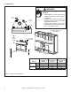
3 Framing and Clearances Note: • • • WARNING Illustrations reflect typical installations and are FOR DESIGN PURPOSES ONLY. Illustrations/diagrams are not drawn to scale. Actual installation may vary due to individual design preference. Fire Risk Provide adequate clearance: • Around air openings. • For service access. Locate appliance away from traffic areas. A.
B. Construct the Appliance Chase A chase is a vertical boxlike structure built to enclose the gas appliance and/or its vent system. Vertical vents that run on the outside of a building may be, but are not required to be, installed inside a chase. Construction of the chase may vary with the type of building. These instructions are not substitutes for the requirements of local building codes. Local building codes MUST be checked.
C. Clearances WARNING Fire Risk Odor Risk • 1/2 in. (13 mm) Install appliance on hard metal or wood surfaces extending full width and depth of appliance. Do NOT install appliance directly on carpeting, vinyl, tile or any combustible material other than wood. Do NOT place furniture or any other combustible household objects within 36 in. of the appliance front. • 1/2 in. (13 mm) • Drywall 0 in. Combustible flooring may be installed next to the front of the appliance. 30 in.
D. Mantel Projections 30 in. minimum to ceiling Top of Appliance Drywall A 18 17 16 15 13 3 - 12 0-3 B 17-3/4 14 17 Mantel Leg or Perpendicular Wall 16-1/4 15-1/2 14-3/4 14 A 1 in. (25mm) min. to perpendicular wall 13-1/4 9-3/8 B 3-1/2 in. (89 mm) min. from fireplace opening to perpendicular wall Measured from top of hood (in inches) Figure 3.3 48 in. (1219 mm) max. Clearances to Mantels or Other Combustibles Above Appliance Figure 3.
4 Termination Locations A. Vent Termination Minimum Clearances WARNING Figure 4.1 specifies minimum vent heights for various pitched roofs. 8 ft (2.44 mm) Termination Cap Storm Collar Roof Flashing Vertical wall Lowest Discharge Opening Gas, Wood or Fuel Oil Termination X 8 ft (2.44 m) Roof Pitch is X / 12 Roof Pitch H (Min.) Ft. Roof Pitch H (Min.) Ft. Flat to 6/12 1.0* Over 11/12 to 12/12 4.0 Over 6/12 to 7/12 1.25* Over 12/12 to 14/12 5.0 Over 7/12 to 8/12 1.5* Over 14/12 to 16/12 6.
5 Vent Information and Diagrams A. Vent Guidelines CAUTION ALL vent configuration specifications MUST be followed. • This product is tested and listed to appliance and vent manufacturer’s specifications. • Appliance performance will suffer if specifications are not followed. WARNING Fire Risk Asphyxiation Risk This appliance requires the specified pipe for operation. • Incorrect pipe may cause spillage, condensation and overheating. These models require the following size B-Vent double wall vent pipe.
Vent supports are per vent manufacturer’s specifications. Maximum horizontal 20 ft (6.1 m) Metal Plumbers' Strap Maximum horizontal run is 50% of vertical. Horizontal run cannot be more than 20 ft. (6.1 m). 45° Elbow Offsets exceeding 45° adapt horizontal limitations 90° Elbow Figure 5.2 Note: Maximum horizontal distance is 50% of vertical vent height. Maximum Horizontal Run WARNING Fire Risk Explosion Risk Insulation and other combustibles must not infringe on clearances.
6 Vent Clearances and Framing A. Pipe Clearances to Combustibles B. Wall Penetration Framing WARNING Do not pack with insulation or other materials. Fire Risk Explosion Risk Maintain vent clearance to combustibles as specified. • Do not pack air space with insulation or other materials. • National building codes recommend using attic shield to keep loose materials/ insulation from contacting vent. Failure to keep insulation or other materials away from vent pipe may cause fire.
7 Appliance Preparation CAUTION CAUTION Risk of Smoke Spillage Outside air inlet must be located to prevent blockage from: • Leaves • Snow/ice • Other debris Blockage may cause combustion air starvation. Sharp Edges • Wear protective gloves and safety glasses during installation. A. Installing Outside Air Kit Damper Assembly WARNING Fire Risk Asphyxiation Risk Maintain vent clearance to combustibles as specified. • Do not pack air space with insulation or other materials.
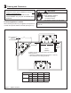
B. Gas and Electrical Connections Ensure that gas and electrical connections are installed at this time. Refer to Sections 9 and 10. C. Securing and Leveling Appliance WARNING Fire Risk! • • Prevent contact with sagging, loose insulation. Do NOT install against combustible materials such as exposed insulation, plastic and insulation backer. The diagram shows how to properly position, level, and secure the appliance (see Figure 7.3).
8 Installing Vent Pipe A. Assemble Vent Sections C. Securing Vent Sections This B-Vent appliance requires 6 in. B-vent double-wall pipe. Follow the pipe manufacturer’s installation guidelines when installing the appliance. This will ensure proper operation and prevent safety hazards. Secure vent sections with vent supports following B-vent manufacturer’s instructions. WARNING WARNING Fire Risk Exhaust Fumes Risk Impaired Performance of Appliance.
9 Gas Information A. Fuel Conversion C. Gas Connection Before making gas connections ensure appliance being installed is compatible with the available gas type. Any natural or propane gas conversions necessary to meet the appliance and locality needs must be made by a qualified technician using Hearth & Home Technologies specified and approved parts. B. Gas Pressure Proper input pressures are required for optimum appliance performance. Gas line sizing requirements need to be made following NFPA51.
• A small amount of air will be in the gas supply lines. When first lighting appliance it will take a short time for air to purge from lines. When purging is complete the appliance will light and operate normally. WARNING Fire Risk Explosion Risk • Gas build-up during line purge may ignite. • Purge should be performed by qualified technician. • Ensure adequate ventilation. • Ensure there are no ignition sources such as sparks or open flames. D. High Altitude Installations U.L.
10 Electrical Information A. Recommendation for Wire This appliance requires 110-120 VAC to be wired to the junction box either for use of optional accessories (standing pilot ignition) or for proper operation of the appliance (Intellifire ignition). Refer to Figure 10.1 to determine if the appliance uses an Intellifire ignition system or standing pilot ignition system. Open the control access panel to view wiring system and gas valve.
Battery Pack WALL SWITCH Ignitor Control Box To Junction Box High Limit Switch ORG Flame Sensor Pilot 3V Adapter GRN* BLK WHT BLK RED WHT BLU BLK BRN ORG RED * GRN wire only used with optional wall switch WSK-MLT-HTL GRN Valve Figure 10.2 Intellifire Pilot Ignition (IPI) Wiring Diagram D. Standing Pilot Ignition System Wiring • This standing pilot ignition system wiring does not require a 110 VAC supply to operate. See Figure 10.3 for the wiring diagram.
E. Junction Box Installation • • • • Remove the junction box assembly from the valve compartment. If the box is being wired from the OUTSIDE of the appliance; - Loosen two screws on the Romex connector, feed the necessary length of wire through the connector and tighten the screws. - Make all necessary wire connections to the receptacle and assemble the receptacle and cover to the junction box. - Attach the junction box assembly to the outside of the appliance with the two screws provided.
11 Finishing A. Mantel Projections B. Facing Material Figure 11.1 shows the minimum vertical and corresponding maximum horizontal dimensions of appliance mantels or other combustible projections above the top front edge of the appliance. WARNING Fire Risk Do NOT obstruct air inlets. Finishing materials must not interfere with: • Air flow through inlets. • Access for service. 30 in.
12 Appliance Setup A. Remove the Shipping Materials Placing the Lava Rock and Vermiculite Remove shipping materials from inside or underneath the firebox. • • B. Clean the Appliance Clean/vacuum any sawdust that may have accumulated inside the firebox or underneath in the control cavity. • Place lava rock on top of the lava rock tray in front of and under the burner. See Figure 12.1. Sprinkle vermiculite evenly over area covered by lava rock. See Figure 12.2.
F. Log Removal/Replacement Log set should look similar to that in Figure 12.4. Figure 12.7 Clear Lava Rock Figure 12.4 Geneva Log Set • Remove/open the lava rock tray as shown in Figures 12.5 and 12.6. Clear the lava rock as shown in Figure 12.7. Remove log/grate assembly from the hearth pan by removing three screws (one per side, one center back behind hearth log). See Figures 12.8 and 12.9. Lift up on log/grate assembly to remove it from appliance and set aside.
G. Glass Doors H. Hood WARNING Handle glass with care. • Inspect the gasket to ensure it is undamaged. • Inspect the glass for cracks, chips or scratches. • Do NOT strike, slam or scratch glass. • Do NOT operate appliance with glass assembly removed, cracked, broken or scratched. • Replace glass assembly as a complete assembly. If you have decided to install optional doors on your appliance, please use them correctly.
13 Operating Instructions A. Before Lighting Appliance Before lighting this appliance, determine if it has a standing pilot or Intellifire ignition system by opening the control access panel to view wiring system and gas valve. If this appliance has a red or black ignitor button (See Figure 10.1) this appliance has a standing pilot ignition system. If there is no red or black ignitor button, this appliance has an Intellifire ignition system.
B. Check Appliance Draft C. High Limit Safety Switch Check draft of appliance to verify proper venting conditions. A high limit switch has been installed on this appliance. This switch automatically turns off the appliance if it becomes too hot. If this happens, do not attempt to operate the appliance until it has been examined by a qualified service technician. For the high limit switch location, see Figures 13.2-13.4. • • • • • Close all windows and doors, turn on all exhaust fans in home.
D. Lighting the Appliance Intellifire Ignition FOR YOUR SAFETY READ BEFORE LIGHTING WARNING: A. B. If you do not follow these instructions exactly, a fire or explosion may result causing property damage, personal injury or loss of life. This appliance is equipped with an ignition device which automatically lights the pilot. Do not try to light the pilot by hand. BEFORE LIGHTING smell all around the appliance area for gas.
7 ON OFF 8 OF F 11 Due to high surface termperatures, keep children, clothing and furniture away. Keep burner and control compartment clean. See installation and operating instructions accompanying the appliance. 29097D Turn manual gas valve to "CLOSED position. Do not force. Replace control access panel. 5 ON 3. 4. 5 OT Turn off wall switch or set thermostat to lowest setting. Remove control access panel. TO TURN OFF GAS TO APPLIANCE 4. OPEN 3. CLOSED PIL 1. 2.
E. After the Appliance is Lit CAUTION Initial Break-in Procedure When you light the appliance, you may notice that it produces heat which does have an associated odor or smell. If you feel this odor is excessive it may require the initial three to four hour continuous burn on high followed by a second burn up to 12 hours to fully drive off any odor from paint and lubricants used in the manufacturing process. Condensation of the glass is normal.
14 Troubleshooting With proper installation, operation and maintenance your gas appliance will provide years of trouble-free service. If you do experience a problem, this troubleshooting guide will assist a qualified service person in the diagnosis of a problem and the corrective action to be taken. This troubleshooting guide can only be used by a qualified service technician. A. Standing Pilot Ignition System Symptom 1. 2.
Symptom Possible Causes Corrective Actions 4. Frequent pilot outage problem. A. Pilot flame may be too high, too low, or blowing (high), causing pilot safety to drop out. Clean and adjust the pilot flame for maximum flame impingement on thermocouple. Follow lighting instructions carefully. 5. The pilot and main burner extinguish while in operation. A. No LP in the tank. Check the LP (propane) tank. Refill the fuel tank. B. Inner vent pipe is leaking exhaust gases back into the system.
B. Intellifire Ignition System Symptom 1. 2. 3. The ignitor/module makes noise, but no spark. Pilots won’t light, there is no noise or spark. Pilot lights but continues to spark, and main burner will not ignite. (If the pilot continues to spark after the pilot flame has been lit, flame rectification has not occurred.) Possible Causes Corrective Actions A. Incorrect wiring.
Symptom 4. 36 Pilot sparks, but pilot will not light. Possible Causes Corrective Actions A. Correct gas supply. Verify that incoming gas line ball valve is “open”. Verify that inlet pressure reading is within acceptable limits, inlet pressure must not exceed 14 in. w.c. B. Ignitor gap is too large. Verify that spark gap from ignitor to pilot hood is .17 in. or 1/8 in. C. Module is not grounded. Verify module is securely grounded to metal chassis of appliance. D.
15 Maintaining and Servicing the Appliance Although the frequency of appliance servicing and maintenance will depend on use and the type of installation, a qualified service technician should perform an appliance check-up at the beginning of each heating season. WARNING Risk of injury or property damage Before servicing: • Turn off gas. • Turn off electricity to appliance. • Disable remote control, if one is present. • Ensure appliance is completely cooled.
Maintenance and Service Tasks: Inspect Doors, surrounds and fronts Gasket seal, glass assembly and glass Valve compartment and firebox top Logs Firebox Burner ignition and operation Venting Remote controls 38 Maintenance Tasks 1. Assess condition of screen and replace as necessary. Recommend addition of screen if one is not present. 2. Inspect for scratches, dents or other damage and repair as necessary. 3. Verify no obstructions to airflow through the louvers. 4.
16 Reference Materials A. Appliance Dimension Diagram Dimensions are actual appliance dimensions. Use for reference only. For framing dimensions and clearances refer to Section 3. C Outside Air 23-1/8 in. (587 mm) 10 in. (254 mm) 13-1/4 in. (336 mm) A 39-1/8 in. (994 mm) Outside Air Gas Access Electric Access 39-1/2 in. (1003 mm) 30 in. (762mm) 2-3/4 in. (70 mm) 13-1/4 in. (337 mm) B 4-3/8 in. (111 mm) 7 in. (178 mm) Model GB4336 GB4942 3-1/8 in. (79 mm) A B C in. 41 in. 36 in.
B. Service Parts List Service Parts Exploded Parts Diagram 36 in.
GB4336 SERIES Service Parts Beginning Manufacturing Date: 1/19/04 Ending Manufacturing Date: Active Service Parts List 36 in. Geneva Gas Fireplace # Description of Part GB4336 GB4336L GB4336I GB4336IL Qty.
GB4336 SERIES Service Parts Beginning Manufacturing Date: 1/19/04 Ending Manufacturing Date: Active Service Parts List 36 in.
GB4336 SERIES Service Parts Beginning Manufacturing Date: 1/19/04 Ending Manufacturing Date: Active Service Parts List 36 in. Geneva Gas Fireplace # Description of Part GB4336 GB4336L GB4336I GB4336IL Valve Assembly Qty.
GB4942 SERIES Service Parts Beginning Manufacturing Date: 1/19/04 Ending Manufacturing Date: Active Exploded Parts Diagram 42 in.
GB4942 SERIES Service Parts Beginning Manufacturing Date: 1/19/04 Ending Manufacturing Date: Active Service Parts List 42 in. Geneva Gas Fireplace # Description of Part Log/Grate Assembly GB4942 GB4942L GB4942I GB4942IL Qty.
GB4942 SERIES Service Parts Service Parts List 42 in.
GB4942 SERIES Service Parts Beginning Manufacturing Date: 1/19/04 Ending Manufacturing Date: Active Service Parts List 42 in. Geneva Gas Fireplace # Description of Part Valve Assembly GB4942 GB4942L GB4942I GB4942IL Qty.
C. Optional Components * 4 in. AK14 - Air Kit ID4 Insulated Duct 4 in. (102 mm) 42 in. (1067 mm) RC-SMART-HTL Remote Control RCT-MLT-HLT Multifunctional Remote RC-BATT-HTL Battery Operated Remote Control (Standing Pilot) SMART-STAT-HTL Remote control with Thermostat Control SMART-BATT-HTL Battery-operated Remote Control with Thermostat Control UD4 Uninsulated Duct 4 in. (102 mm) 42 in.
This page intentionally left blank.
This page intentionally left blank.
D. Limited Lifetime Warranty Gas Appliance (Fireplace) Limited Lifetime Warranty HEARTH & HOME TECHNOLOGIES INC. (“HHT”) extends the following warranty for HEATILATOR® gas appliances installed in the United States of America or Canada (the "Appliance"). Dealers and employees of HHT have no authority to make any warranty or authorize any remedies in addition to or inconsistent with the terms of this warranty.
E. Contact Information Hearth & Home Technologies Inc. 1915 W. Saunders Street Mt. Pleasant, Iowa 52641 www.heatilator.com Please contact your Heatilator dealer with any questions or concerns. For the number of your nearest Heatilator dealer, place call 1-800-927-6841. - NOTES - CAUTION Important operating • and maintenance instructions included. Read, understand • and follow these instructions for safe installation and operation. L e a v e t h i s manual with party responsible for use and operation.