Owner’s Manual Installation and Operation Models: NDI30 NDI30-SP NDI35 NDI35-SP NDI30-SPFK NDI35-SPFK NOTICE DO NOT DISCARD THIS MANUAL • Important operating and maintenance instructions included. • Read, understand and follow these instructions for safe installation and operation. WARNING: If the information in these instructions is not followed exactly, a fire or explosion may result causing property damage, personal injury, or death.
Read this manual before installing or operating this appliance. Please retain this owner’s manual for future reference. A. Congratulations This Owner’s Manual should be retained for future reference. We suggest that you keep it with your other important documents and product manuals. Congratulations on selecting a Heatilator gas fireplace, an elegant and clean alternative to wood burning fireplaces.
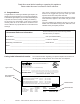
Safety Alert Key: • • • • DANGER! Indicates a hazardous situation which, if not avoided will result in death or serious injury. WARNING! Indicates a hazardous situation which, if not avoided could result in death or serious injury. CAUTION! Indicates a hazardous situation which, if not avoided, could result in minor or moderate injury. NOTICE: Used to address practices not related to personal injury. Table of Contents A. Congratulations . . . . . . . . . . . . . . . . . . . . . . . . . . . . . . . . .
B. Limited Lifetime Warranty Hearth & Home Technologies Inc. LIMITED LIFETIME WARRANTY Hearth & Home Technologies Inc., on behalf of its hearth brands (”HHT”), extends the following warranty for HHT gas, wood, pellet, coal and electric hearth appliances that are purchased from an HHT authorized dealer.
B.
1 Listing and Code Approvals A. Appliance Certification D. High Altitude Installations MODELS: NDI30, NDI30-SP, NDI35, NDI35-SP, NDI30-SPFK, NDI35-SPFK LABORATORY: Underwriters Laboratories, Inc. (UL) TYPE: Vented Gas Fireplace Heater Vented Gas Fireplace Heaters This product is listed to ANSI standards for “Vented Gas Appliance Heaters” and applicable sections of “Gas Burning Heating Appliances for Manufactured Homes and Recreational Vehicles”, and “Gas Fired Appliances for Use at High Altitudes”.
2 Operating Instructions User Guide A. Gas Fireplace Safety • Keep remote controls out of reach of children. • Never leave children alone near a hot fireplace, whether operating or cooling down. WARNING • Teach children to NEVER touch the fireplace. HOT SURFACES! Glass and other surfaces are hot during operation AND cool down. • Consider not using the fireplace when children will be present. Hot glass will cause burns.
C. Clear Space E. Fixed Glass Assembly WARNING! DO NOT place combustible objects in front of the fireplace or block louvers. High temperatures may start a fire. See Figure 2.2. See Section 12.H. Avoid placing candles and other heat-sensitive objects on mantel or hearth. Heat may damage these objects. F.
H. Lighting Instructions (IPI) The IPI system may be operated with two D-cell batteries. When using batteries, unplug the transformer. To prolong battery life, remove them when using the transformer. FOR YOUR SAFETY READ BEFORE LIGHTING LIGHTING INSTRUCTIONS (IPI) WARNING: If you do not follow these instructions exactly, a fire or explosion may result causing property damage, personal injury or loss of life. 1. This appliance is equipped with an ignition device which automatically lights the burner.
I. Lighting Instructions (Standing Pilot) FOR YOUR SAFETY READ BEFORE LIGHTING WARNING: If you do not follow these instructions exactly, a fire or explosion may result causing property damage, personal injury or loss of life. A. This appliance has a pilot which must be lighted by hand. When lighting the pilot, follow these instructions exactly. B. BEFORE LIGHTING, smell all around the appliance area for gas. Be sure to smell next to the floor because some gas is heavier than air and will settle on the floor.
J. After Appliance is Lit Initial Break-in Procedure • The appliance should be run three to four hours continuously on high. • Turn the appliance off and allow it to completely cool. • Remove fixed glass assembly. See Section 12.H. • Clean fixed glass assembly. See Section 3. • Replace the fixed glass assembly and run continuously on high an additional 12 hours. This cures the materials used to manufacture the fireplace. NOTICE! Open windows for air circulation during appliance break-in.
3 Maintenance and Service Any safety screen or guard removed for servicing must be replaced prior to operating the appliance. Doors, Surrounds, Fronts Frequency: Annually When properly maintained, your appliance will give you many years of trouble-free service. We recommend annual service by a qualified technician. By: Homeowner A. Maintenance Tasks-Homeowner • Inspect for scratches, dents or other damage and repair as necessary. Installation and repair should be done by a qualified technician only.
Venting Control Compartment and Firebox Top Frequency: Seasonally Frequency: Annually By: Homeowner By: Service Technician Tools needed: Protective gloves and safety glasses. Tools needed: Protective gloves, vacuum cleaner, dust cloths • Inspect venting and termination cap for blockage or obstruction such plants, bird nests, leaves, snow, debris, etc. • Verify termination cap clearance to subsequent construction (building additions, decks, fences, or sheds). See Section 6.
Burner Ignition and Operation Frequency: Annually By: Service Technician Tools needed: Protective gloves, vacuum cleaner, whisk broom, flashlight, voltmeter, indexed drill bit set, and a manometer. • Verify burner is properly secured and aligned with pilot or igniter. • Clean off burner top, inspect for plugged ports, corrosion or deterioration. Replace burner if necessary. • Replace Glowing embers with new dime-size pieces. DO NOT block ports or obstruct lighting paths.
4 Getting Started Installer Guide A. Typical Appliance System NOTICE: Illustrations and photos reflect typical installations and are for design purposes only. Illustrations/diagrams are not drawn to scale. Actual product may vary from pictures in manual VERTICAL TERMINATION CAP (SECTION 8.F) VENT PIPE (SECTION 8) 3 INCH FLEX LINERS (SECTION 8) MANTEL AND MANTEL LEG SECTION 5.B AND 11.A SURROUND OR FRONT NOT SHOWN SECTION 2.D AND 8.D.
B. Design and Installation Considerations D. Inspect Appliance and Components Heatilator gas inserts are designed for installations into solid fuel masonry or factory built fireplaces that have been installed in accordance with the National, Provincial, State and local building codes. Fireplaces are to be constructed of non-combustible materials and, in the absence of local or regional codes, meet criteria of NFPA 211. No additional outside air source is required.
5 Fireplace Size Requirements A. Minimum Fireplace Opening from the factory built firebox if attached with mechanical fasteners. Minimum fireplace opening requirements for a standard 3/4 inch deep surround are shown in Figure 5.1. For smaller openings, an optional 1-1/2 inch deep surround is available and dimensions are shown in Figure 5.2. • The metal floor of the solid fuel firebox may be removed to facilitate the installation of the insert.
SIDE VIEW TOP VIEW 1-1/2 IN. BD AD CD SURROUND SURROUND APPLIANCE APPLIANCE MINIMUM FIREPLACE SIZE Location NDI35 NDI30 Inches Millimeters Inches Millimeters AD Alternate Unit Width 33-3/16 843 29-1/16 738 BD Alternate Unit Depth 15-1/16 383 13-7/8 352 CD Alternate Unit Height 22-9/16 573 19-1/16 484 * Note: If exhaust collar on insert and fireplace damper do not line up, add 4 inches (102 mm) to minimum fireplace height for bends in vent pipe. Figure 5.
6 Termination Locations A. Vent Termination Minimum Clearances A WARNING Fire Risk. Maintain vent clearance to combustibles as specified. • DO NOT pack air space with insulation or other materials. Failure to keep insulation or other materials away from vent pipe may cause fire. B 6 in. (minimum) up to 20 in. 152 mm/508 mm 18 in. minimum 457 mm 20 in. and over 0 in. minimum Gas, Wood or Fuel Oil Termination Cap B A* HORIZONTAL OVERHANG 2 FT. MIN. 20 INCHES MIN.
7 Installation Preparation Prepare the existing solid fuel masonry or factory built non-combustible firebox for installation. A. Inspection and Cleaning Prior to installing the gas insert: D. Fireplace Conversion Notice Permanently attach the label with the following warning to the inside lower back of the fireplace firebox into which the insert is being installed. Silicone or mechanical fasteners may be required to properly secure the label.
8 Installing Vent Pipe and Appliance A. Vent Limits B. Venting Components The abbreviations listed in this vent table key are used in the vent diagrams. CAUTION! Risk of Cuts/Abrasions/Flying Debris. Wear protective gloves and safety glasses during installation. Sheet metal edges are sharp. Description Minimum Vertical Run Length 10 ft. The vertical vent termination system installed on this model includes: Maximum Vertical Run Length 50 ft.
CUT AND BEND FLASHING AS NEEDED TO FIT CHIMNEY SEALANT ADHESIVE WARNING! Risk of Fire! Only an approved Hearth & Home Technologies surround may be used to cover integral grills on solid fuel burning fireplaces. No other components such as shrouds, sheetmetal plates, etc., may be used to seal off vents.
F. Installing Adaptor and Termination Cap For installation of termination cap see minimum vent heights for various pitched roofs (see Figure 8.4) . To install adaptor see Figure 8.5. CAUTION! Risk of Cuts/Abrasions/Flying Debris. Wear protective gloves and safety glasses during installation. Sheet metal edges are sharp. Damper Flashing Kit (Optional) For use with LINK-DV30B or LINK-DV4-30B Liner Kit. Note: Damper may have to be removed to use this kit. HORIZONTAL OVERHANG 2 FT. MIN. 20 INCHES MIN.
9 Gas Information A. Fuel Conversion C. Gas Connection • Make sure the appliance is compatible with available gas types. • Refer to Reference Section 14 for location of gas line access in appliance. • Conversions must be made by a qualified technician (NFI certified or factory-trained) using Hearth & Home Technologies specified and approved parts. • Gas line may be run through knockout(s) provided. B. Gas Pressure • Optimum appliance performance requires proper input pressures.
10 Electrical Information A. Wiring Requirements B. Standing Pilot Ignition System Wiring NOTICE: This appliance must be electrically wired and grounded in accordance with local codes or, in the absence of local codes, with National Electric Code ANSI/NFPA 70-latest edition or the Canadian Electric Code CSA C22.1. • This appliance comes standard with a 120 VAC cord assembly which has a female plug in to accommodate all control options and accessories. See Figure 10.5.
INTERMITTENT PILOT IGNITOR IGNITION MODULE 3 VAC I S TRANSFORMER 3 VAC TO CORD ASSEMBLY 110V ORG WHT GROUND TO FIREPLACE CHASSIS CK A BL D BATTERY PACK REMOTE WIRE ASSEMBLY GREEN ORANGE BRN BRN RE VALVE WALL SWITCH OR REMOTE CONTROL NOTE: 1/4 IN. FEMALE SPADE CONNECTORS CONNECT TO THE REMOTE WIRE ASSEMBLY ON OFF ON/OFF SWITCH Figure 10.2 IPI Wiring Diagram PILOT ASSEMBLY THERMOCOUPLE THERMOPILE PIEZO RED VALVE WHT ROCKER SWITCH OPTIONAL WALL SWITCH, THERMOSTAT OR REMOTE Figure 10.
D. Optional Accessories Requirements • This appliance may be used with a wall switch, wall mounted thermostat, blower and/or a remote control. • To connect optional accessories, the supplied cord assembly should be used. See Figure 10.5 for a wiring diagram for a blower or remote. Wiring for optional Hearth & Home Technologies approved accessories should be done now to avoid reconstruction. Follow instructions that come with those accessories. • Plug the cord into a convenient outlet.
E. Installation for Fan (Optional) On units already installed, removal of decorative front, surround and gas insert is required. • Detach flexible liner from back of unit if insert is installed. • Remove the four screws on the cover plate (see Figure 10.6). • Install and wire the blower per instruction shipped with the blower. Figure 10.5 also shows a wiring diagram. • Reinstall the cover plate back on the unit. Make sure the fan does not make contact with the back wall to prevent noise from vibration.
11 Finishing A. Mantel and Wall Projections WARNING! Risk of Fire! Comply with all minimum clearances to combustibles as specified. Framing or finishing material closer than the minimums listed must be constructed entirely of noncombustible materials (i.e., steel studs, concrete board, etc). EXISTING NON-COMBUSTIBLE FACING 12 IN. MAX. Clearance to combustible material under the insert is 1/4 inch (6 mm). Clearance from top of fireplace opening for combustibles extending 12 inches max. is 12 inches.
12 Appliance Setup A. Remove Glass Assembly F. Ember Placement See Section 12.H. WARNING! Risk of Explosion! Follow ember placement instructions in manual. DO NOT place embers directly over burner ports. Replace ember material annually. Improperly placed embers interfere with proper burner operation. B. Remove the Shipping Materials Remove shipping materials from inside or underneath the firebox. C.
G. Install the Log Assembly Log Set Assembly: LOGS-NDI30 Models: NDI30, NDI30-SP CAUTION: Logs are fragile, handle with care. SRV2226-701 PILOT BRACKET LOG SHELF SRV2226-705 SRV2226-704 SRV2226-706 SRV2226-703 SRV2226-702 FLAT SPOT FOR LOG #4 LOG PINS FLAT SPOT FOR LOG #5 FLAT SPOT FOR LOG #6 1 GRATE BAR LOG NOTCH GRATE TINES Figure 2. Install Log #1 Figure 1. Log #1 (SRV2226-701) Position Log #1 as shown in Figure 2. Note additional placement instructions in Figure 1.
LOG TOUCHES GRATE TINE 3 MATE LOG PIN WITH LOG SLOT Figure 5. Place Log #3 SLOT Figure 6. Log #3 Log #3 (SRV2226-706): Position Log #3 as shown in Figure 5. Refer to Figure 1 and Figure 6 for location of reference points. Mate the slot located on the bottom of Log #3 with the log pin located on the left side of the burner. Move the left end of Log #3 forward until it comes into contact with the grate tine.
G. Install the Log Assembly Log Set Assembly: LOGS-NDI35 Models: NDI35, NDI35-SP SRV2224-701 SRV2224-704 SRV2224-703 SRV2224-702 SRV2224-706 SRV2224-705 Figure 1. Log Set Installed LOG SUPPORT 1 LOG PINS BASE TINE GRATE TINES Figure 2. Figure 3. Install Log #1 CAUTION: Logs are fragile, handle with care. Log #1 (SRV2224-701) Position Log #1 as shown in Figure 3. Note additional references in Figure 2. Set the log on the log support.
FLAT SPOT FOR LOG #5 GRATE TINE SLOT LOG PIN MATES WITH LOG SLOT FLAT SPOT FOR LOG #6 LOG SLOT 3 RIGHT GRATE TINE MATES WITH LOG SLOT Figure 7. Log #3 Figure 6. Log #3 Log #3 (SRV2224-702): Position Log #3 as shown in Figure 6. Refer to Figure 2 and Figure 7 for location of reference points. Mate the log slot located on the bottom of Log #3 with the right log pin located on the burner top. Rotate the right end of Log #3 forward until it contacts with the right grate tine.
H. Fixed Glass Assembly I. Air Shutter Setting Removing Fixed Glass Assembly Air shutter settings should be adjusted by a qualified service technician at the time of installation. The air shutter is set at the factory for minimum vertical vent run. Adjust air shutter for longer vertical runs. See Figure 12.4. WARNING! Risk of Asphyxiation! Handle fixed glass assembly with care. Inspect the gasket to ensure it is undamaged and inspect the glass for cracks, chips or scratches.
13 Troubleshooting With proper installation, operation, and maintenance your gas appliance will provide years of trouble-free service. If you do experience a problem, this troubleshooting guide will assist a qualified technician in the diagnosis of a problem and the corrective action to be taken. This troubleshooting guide can only be used by a qualified technician. Contact your dealer to arrange a service call by a qualified technician. A.
Troubleshooting (continued) Symptom Possible Cause 3. (Continued) Corrective Action C. Valve. Turn the valve knob to the ON position. Place the ON/ OFF switch in the ON position. Take a reading with a millivolt meter at the thermopile terminals. The millivolt meter should read greater than 125mV. If the reading is acceptable, and if the burner does not come on, replace the gas valve. D. Plugged burner orifice. Check the burner orifice for stoppage. Remove stoppage. E. Wall switch or wires.
B. IntelliFire Ignition System Symptom Possible Cause 1. Pilot won’t light. A. Incorrect wiring. The ignitor/module makes noise, but no B. Loose connections or electrical spark. shorts in the wiring. 2. Pilot won’t light, there is no noise or spark. 3. Pilot sparks, but Pilot will not light. 38 Corrective Action Verify “S” wire (white) for sensor and “I” wire (orange) for ignitor are connected to correct terminals on module and pilot assembly.
Symptom Possible Cause 4. Pilot lights but continues to spark, and main burner will not ignite. (If the pilot continues to spark after the pilot flame has been lit, flame rectification has not occurred.) A. A shorted or loose connection in flame sensing rod. Corrective Action Verify all connections to wiring diagram in manual. Verify connections underneath pilot assembly are tight.
14 Reference Materials A. Appliance Dimension Diagram Dimensions are actual appliance dimensions. Use for reference only.
B. Vent Kits Components Direct Vent Flex Liner Kits (see Figure 14.2) LINK-DV30B: Masonry 3 inch flex liner kit. Expands to 30 feet. Includes: two liners, termination cap, flashing, and link adapter. LINK-DV4-30B: Masonry 3 inch flex liner kit. Expands to 30 feet and 4 feet respectively. Includes: two liners, termination cap, flashing, and link adapter. FLASH-DAMP LINK-ZC-ADP LINK-DV30B DV-46DVA-GK FLEX3-30 LINK-DV4-30B Figure 14.
D. Contact Information Heatilator, a brand of Hearth & Home Technologies Inc. 7571 215th Street West, Lakeville, MN 55044 www.heatilator.com Please contact your Heatilator dealer with any questions or concerns. For the location of your nearest Heatilator dealer, please visit www.heatilator.com.