HeatMaster Installation, Operating and Servicing Instructions HM 60 N / 70 N / 100 N / 150 JUMBO HM 60 N / 70 N / 100 N With ACV BG 2000-S premix gas burner HM 60 N / 70 N / 100 N With ACV BM 101 oil burner HM 150 JUMBO With ACV BM 151 oil burner excellence in hot water 66400501
INDEX INTRODUCTION INTRODUCTION 1 INTENDED USERS OF THESE INSTRUCTIONS Intended users of these instructions Symbols Applicable standards Warnings 1 1 1 1 These instructions are intended for - specifying engineers - installing engineers - end-users - servicing engineers DESCRIPTION 2 Operating principle Construction features 2 2 TECHNICAL SPECIFICATION 5 Essential instruction for operating the system correctly.
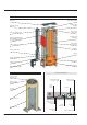
DESCRIPTION OPERATING PRINCIPLE CONSTRUCTION FEATURES The HeatMaster is a high performance, direct fired hot water storage heater, which has indirect heat transfer due to its Tank-in-Tank construction. Outer body At the heart of the HeatMaster is a stainless steel cylinder through which the flue tubes pass. This is surrounded by a mild steel shell containing the primary water (neutral fluid). The outer shell extends down to the combustion chamber and even around the flue tubes.
DESCRIPTION Features of HeatMaster 70 N / 100 N Flue reduction collar Top cover Central heating flow pipe Automatic air vent Domestic hot water outlet Domestic cold water inlet Flue pipes and turbulators Heating circuit filling valve with removable hose and non-return valve Tank-in-Tank heat exchanger Primary expansion vessel Insulation Primary shunt pump Burner Casing front panel Heating return Primary circuit Combustion chamber Burner chamber plate Safety features of the HeatMaster 60 N Co
DESCRIPTION Safety features of the HeatMaster 70 N and 100 N Control panel HeatMaster 70 N and HeatMaster 100 N Thermal reset high limit thermostat Combined temperature and pressure gauge Manual reset high limit thermostat Manual reset high limit thermostat Burner lockout indicator Summer / Winter switch Time clock Low water pressure switch I O Control thermostat Primary circuit low water pressure indicator ON / OFF switch Control thermostat High limit cutoff indicator Primary safety valve
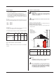
TECHNICAL SPECIFICATION MAXIMUM OPERATING CONDITIONS BURNER CHAMBER PLATE Maximum service pressure (tank full of water) - Primary circuit: 3 bar - Secondary circuit: 10 bar The burner chamber plate has 4 threads (M 10 x 20) for attaching the burner. It is protected from heat by a blanket insulation. Test pressure (tank full of water) - Primary circuit: 4.5 bar - Secondary circuit: 13 bar 5xØ6.
TECHNICAL SPECIFICATION DIMENSIONS The units are delivered fully assembled, tested and packed on a timber base with shockproof edges and protected by heat-shrunk plastic film. On reception and after unpacking, check the equipment for damage. For transport purposes, refer to the weight (page 5) and dimensions given below.
TECHNICAL SPECIFICATION HeatMaster 70 N and HeatMaster 100 N Without burner G With ACV BG 2000-S premix gas burner A F A H B K C/2 J C C D E D HeatMaster 150 Jumbo F A 562 H K C D G J E 7
INSTALLATION BOILER ROOM CHIMNEY CONNECTIONS Important • • • Keep vents free at all times. Do not store inflammable products in the boiler room. Do not store corrosive products near the boiler, such as paints, solvents, chlorine, salt, soap and other cleaning products. If you smell gas, do not switch on the light or light a flame. Turn off the mains gas tap at the meter and inform the appropriate services immediately.
INSTALLATION Balanced flue boiler connection type: C C33 120 C13 150 min. C13: concentric horizontal connection C33: concentric vetical connection C53: parallel chimney connection C63: concentric vertical connection without terminal (only in Germany and Luxembourg). C53 2 m min.
INSTALLATION HOT WATER CONNECTIONS Example of parallel connection Recommended for applications with a high continuous flow. Pressure reducing valve If the mains water pressure is greater than 6 bar, a pressure reducing valve must be fitted. Expansion relief valve The tank expansion relief valve must be ACV approved and calibrated to a maximum of 7 bar. The valve discharge must be connected to the drain. Hot water expansion vessel A hot water expansion vessel must be installed.
INSTALLATION HEATING CONNECTION OIL SUPPLY CONNECTIONS - ACV BM BURNERS The HeatMaster has two connections at the rear that can be used to connect a central heating circuit. Connecting a heating system may reduce the domestic hot water performance. (If another make of buner is fitted please refer to that manufacturers technical manual) Installation without return Expansion max 4m The HM 60 is fitted with an 8 litre expansion vessel.
INSTALLATION ELECTRICAL CONNECTIONS WIRING DIAGRAM Power supply HeatMaster wiring diagram legend 60 N, 70 N, 100 N (page 13) and 150 Jumbo (page 14) The boiler operates with a 230 V - 50 Hz single phase supply. A double pole isolator with a 6 amp fuse or a 6 amp MCB must be fitted outside the boiler to allow power to be shut off during servicing and before any repairs are carried out on the boiler. 1. 2. 3. 4. 5. 6. 7. 8. 9. 10. 11. 12. 13. 14. 15. 16. 17. 18. 19.
INSTALLATION Electrical connection HeatMaster 150 Jumbo Pk. R. V. W. Y. Y/Gr.
COMMISSIONING FILLING THE HOT WATER AND HEATING CIRCUITS HeatMaster 70 N and 100 N C IMPORTANT Hot water tank must be pressurised before the heating circuit is filled. B 1. Close the primary circuit filling valves (A) 2. Open the stop valve (B) and the drawoff tap (C). When water flows out of the tap, the hot water tank is full and the drawoff tap (C) should be closed. 3. Fill the primary (heating) circuit by opening the valves (A) and pressurising to 1 bar. 4.
BURNER FEATURES ACV BG 2000-S PREMIX GAS BURNERS ACV BG 2000-S premix gas burners dimensions Description The burner tube is coated with metal fibre (NIT) which, in addition to its remarkable heat exchange capabilities, gives greater durability. The main components are a venturi and one (model 60 and 70) or two (model 100) gas valves, technology specially developed by Honeywell for low Nox premix air/gas burners with automatic ignition and ionisation flame detection.
BURNER FEATURES Burner electrical connection BG 2000-S/60 and BG 2000-S/70 Electrical connections L1 G Br Y/Gr Gr Bk Y G B Gr Y/Gr B Br Y/Gr Y Br Bk B B Br N T1 T2 S3 B4 Br Blue Black Brown Grey Green Yellow Yellow / Green Br B. Bk. Br. G. Gr. Y. Y/Gr. 1 2 3 4 5 6 7 8 9 10 11 12 L1 N Burner electrical connection BG 2000-S/100 Electrical connections L1 Br Bk Br B Br N T1 T2 S3 B4 B Blue Black Brown Grey Green Yellow Yellow / Green Br B. Bk. Br. G. Gr. Y. Y/Gr.
BURNER FEATURES ACV premix gas burner BG 2000-S/60 and BG 2000-S/70 Ignition electrode Burner chamber plate insulation Burner tube Gas valve Venturi Chamber plate Fan Ionisation probe Potentiometer setting Relay Gas inlet Burner plug connector Fan power plug ACV premix gas burner BG 2000-S/100 Ignition electrode Burner chamber plate insulation Burner tube Gas valve Venturi Chamber plate Fan Potentiometer setting Ionisation probe Relay Gas inlet Fan power plug Burner plug connector 17
BURNER FEATURES HeatMaster 60, 70 and 100 Gas burner features - BG 2000 Input Output Combustion efficiency - natural gas Natural gas CO2 HM 60 N HM 70 N HM 100 N HM 100 N HM 150 Jumbo + BG 2000-S/60 + BG 2000-S/70 + BG 2000-S/100 + gas pressure jet burner + gas pressure jet burner 69.9 63.0 91.2 9.5 69.9 63.0 91.5 9.0 85.0 77.4 92.9 9.0 96.8 90.0 92.9 9.0 154 139.1 91.5 9.0 m3/h 7.40 7.40 8.99 10.24 16.30 m3/h 8.60 8.60 10.46 11.91 18.95 m3/h 2.86 2.86 3.47 3.95 6.
BURNER FEATURES ACV BM 101 AND BM 151 OIL BURNERS Features - Description - The use of new technology enables our medium output burners to meet current performance and emissions quality requirements. These burners are fitted with high quality components including a two-stage oil pump that permits soft start. - Components: - Landis & Gyr relay - A.E.G.
MAINTENANCE SERVICE INTERVALS SERVICING THE BOILER ACV recommends that boilers should be serviced at least once a year. The burner must be serviced and tested by a competent engineer. If a boiler is subject to heavy use, it may require servicing more than once a year - consult ACV for advice. 1. Turn OFF the on/off switch on the boiler control panel and isolate external electrical supply. 2. Turn off the gas or oil supply to the boiler. 3. Remove the flue to gain access to the top of the boiler. 4.
MAINTENANCE SERVICING THE SAFETY DEVICES Draining the hot water circuit - Check that all thermostats and safety devices are working properly. - Test the safety valves on the central heating and hot water circuits. SERVICING THE BURNER Oil burner - Check and if necessary clean the main filter on the oil line. - Check the alignment of the nozzle: check, clean or change the nozzle and its filter, check that the electrodes and flame holder are clean and correctly adjusted.
USER GUIDE USING THE BOILER Control panel HeatMaster 60 N Combined temperature and pressure gauge Your system should be serviced at least once a year by a qualified engineer. If the boiler is subject to heavy use, it may require servicing more than once a year - consult your service engineer for advice.
USER GUIDE Heating system pressure HeatMaster 70 N and 100 N From time to time you may need to top up the heating system pressure. This pressure is indicated by the combined temperature and pressure gauge on the boiler control panel. The minimum pressure when the boiler is cold should be 1 bar.
USER GUIDE RESETTING THE PRESSURE JET OIL OR GAS BURNER • • HM 60 N and HM Jumbo 150 ➠ the lockout indicator is situated on the burner. HM 70 N and 100 N ➠ the lockout indicator is situated on the burner and on the control panel. The red warning light indicates an operating fault. Wait five minutes before resetting the burner. To reset : press the button located on the burner.
SERVICE RECORD INSTALLATION DETAILS Date installed : Flue gas T° : % CO2 (min. load) : Serial number : Efficiency : % ❏ CO2 (max. load) ❏: LPG ❏ Gas Model : Heating system pressure setting : Gas pressure : Name and signature : Oil SERVICE RECORD Date serviced : Flue gas T° : Remarks : % CO2 (min. load) : Efficiency : % ❏ CO2 (max. load) ❏: LPG ❏ Gas Gas pressure : Name and signature : Oil Date serviced : Flue gas T° : Remarks : % CO2 (min. load) : Efficiency : % ❏ CO2 (max.
SERVICE RECORD Date serviced : Flue gas T° : Remarks : % CO2 (min. load) : Efficiency : % ❏ CO2 (max. load) ❏: ❏ Gas Gas pressure : LPG Name and signature : Oil Date serviced : Flue gas T° : Remarks : % CO2 (min. load) : Efficiency : % ❏ CO2 (max. load) ❏: LPG ❏ Gas Gas pressure : Name and signature : Oil Date serviced : Flue gas T° : Remarks : % CO2 (min. load) : Efficiency : % ❏ CO2 (max.
SERVICE RECORD Date serviced : Flue gas T° : Remarks : % CO2 (min. load) : Efficiency : % ❏ CO2 (max. load) ❏: ❏ Gas Gas pressure : LPG Name and signature : Oil Date serviced : Flue gas T° : Remarks : % CO2 (min. load) : Efficiency : % ❏ CO2 (max. load) ❏: LPG ❏ Gas Gas pressure : Name and signature : Oil Date serviced : Flue gas T° : Remarks : % CO2 (min. load) : Efficiency : % ❏ CO2 (max.
SERVICE RECORD Date serviced : Flue gas T° : Remarks : % CO2 (min. load) : Efficiency : % ❏ CO2 (max. load) ❏: ❏ Gas Gas pressure : LPG Name and signature : Oil Date serviced : Flue gas T° : Remarks : % CO2 (min. load) : Efficiency : % ❏ CO2 (max. load) ❏: LPG ❏ Gas Gas pressure : Name and signature : Oil Date serviced : Flue gas T° : Remarks : % CO2 (min. load) : Efficiency : % ❏ CO2 (max.
www.acv-world.com excellence in hot water 13/05/2003 INTERNATIONAL ESPAÑA PORTUGAL ACV international n.v KERKPLEIN, 39 B-1601 RUISBROEK - BELGIUM TEL.: +32 2 334 82 20 FAX: +32 2 378 16 49 E-MAIL: international.info@acv-world.com ACV ESPAÑA C/DE LA TEIXIDORA, 76 POL. IND. LES HORTES E-08302 MATARÓ - ESPANA TEL.:+34 93 759 54 51 FAX:+34 93 759 34 98 E-MAIL: spain.info@acv-world.com BOILERNOX LDA RUA OUTEIRO DO POMAR CASAL DO CEGO, FRACÇÃO C, PAVILHÃO 3 - MARRAZES 2400-402 LEIRIA - PORTUGAL TEL.