
Product Manual

18
Enerco | Heatstar ERXL Series Heater Operating Instructions and Owner’s Manual
SECTION 7
Wiring
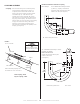
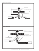
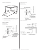
Heatersarenormallycontrolledbythermostats.Linevoltage
thermostatsarewireddirectly(seeFigure15),24Vthermostatsare
wireddirectlyusingtheterminalsonburnerbox(seeFigure16).
HeatersmustbegroundedinaccordancewiththeNationalElectric
CodeANSI/NFPA-70orcurrentCanadianElectricalCode,CSA
C22.1.Heatersmayalsobecontrolledwithamanuallinevoltage
switchortimerswitchinplaceofthethermostat.
FIGURE 15: Line Voltage Thermostat Wiring
T
H
N
120v – 60 Hz
White
White
Green
Green
Supply Circuit
120v – 60 Hz
Supply Circuit
Burners
(Maximum – 2 per Thermostat)
Burners
(Maximum – 1 per Thermostat)
Black
Black
H
N
T
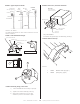
FIGURE 16: Low Voltage Thermostat Wiring
T
H
N
120v – 60 Hz
White
White
Green
Green
Supply Circuit
120v – 60 Hz
Supply Circuit
Burners
(Maximum – 2 per Thermostat)
Burners
(Maximum – 1 per Thermostat)
Black
Black
H
N
T
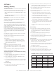
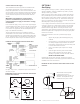
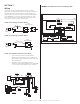
FIGURE 18: Ener-Radiant XL Burner Internal Wiring Ladder
FIGURE 17: Ener-Radiant XL Burner Internal Wiring
• Ifanyoftheoriginalwireassuppliedwiththe
appliancemustbereplaced,itmustbereplacewith
wiringmaterialhavingatemperatureratingofatleast
105°Cand600volts.
• Eachburnermustbeelectricallygroundedin
accordancewiththeNationalElectricCodeANSI/NFPA
-70orcurrentCanadianElectricalCode,CSAC22.1.
Diagram
VAC
120
120V
24V
Black
Black
Purple
Yellow
Yellow
Black
Black
Black
Green
Green
Orange
Transformer
White
White
White
THERMOSTAT
White
Blue
Gas Valve
Air Switch
Ignitor
Sensor
Motor / Blower
Door Switch
Terminal
Bushing
120V
L2
(NEUTRAL)
White
White
White
White
White
White
Gray
Orange
Transfomer
Thermostat
Air Switch
Gas Valve
Door Switch
Motor / Blower
Ignitor
Sensor
Blue
Yellow
Yellow
Purple
Black
Black
Black
Black
L2 (HOT)
24V