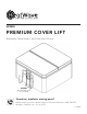
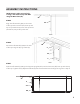
. NP5880 PREMIUM COVER LIFT Assembly, Installation, and Use Instructions NP5880 (Spa and spa cover not included) B. Rotate the arms outward and make the spring lock. Beforesure returning to your retailer,pins call our Consumer Hotline at 1-800-759-0977, Questions, problems, missing parts? Monday – Friday, 8 a.m. – 5 p.m. (CST).
THANK YOU! Thank you for purchasing this product! We work around the clock and around the globe to ensure that our products maintain the highest possible quality. However, in the rare case of issues during assembly or use of this product, please contact our Consumer Hotline at 1-800-759-0977 for immediate assistance before contacting your retailer. Please read the warranty information at the end of this User Manual for further details.
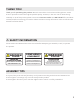
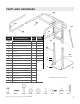
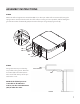
1. Lay out all the parts and verify that they are all present according to the Cover Caddy Parts and Hardware List. See Fig 1. Cover Caddy Installation Instructions Cover Cover Cover Cover Cover Caddy Caddy Caddy Caddy Caddy Cover Installation Installation Installation Installation Installation Caddy Instructions Installation Instructions Instructions Instructions Instructions Instructions PARTS AND HARDWARE Cover Caddy Installation Instructions EE 1. Lay out1.
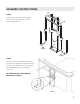
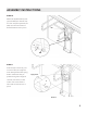
ASSEMBLY INSTRUCTIONS NOTE:SKIP IF YOUTO ARE USING NOTE: IF USING A SIDE MOUNT SETUP, STEP 5. A SIDE MOUNT SETUP, SKIP TO STEP 6 2. Attach the ccGG Support Legs to the ccFF Base Plate using the ccA Round Head Bolts, the ccG Washer and the ccN Round Head Nuts. See Fig 2. STEP 1 Attach the Support Uprights (GG) to the Base Plate (FF) using the Round Head Bolts (A), Washers (G), and the Round Head Nuts (N). GG FF N G A Figure 2 3.
ASSEMBLY INSTRUCTIONS AA STEP 3 Slide the legs of the Lift Assembly (AA), Slide the legs of the ccAA Main Unit/ccEE Pivot Arm assembly over the ccGG Support Legs. See with Pivot Arm (EE) attached, over4.the Fig 4. EE Support Uprights (GG). GG FF BB (Step 8) STEP 4 Figure 4 5. Loosely thread the ccE Adjustment Bolt through the ccH AdjustmentCC Bolt Washer and into the threaded holes in the Support Legs. DO NOT tighten the adjustment screws yet.(Step See Fig 8)5.
SIDE MOUNT ONLY 6. Align the Main Unit assembly in the center of the spa. Line up the Pivot Arm as shown in Fig 6. Mark the screw holes.. SIDE MOUNT ONLY ASSEMBLY INSTRUCTIONS 6. Align the Main Unit assembly in the center of the spa. Line up the Pivot Arm as shown in Fig 6. Mark the screw holes.. NOTE: Steps 5 and 6 are used only if using a side mount setup and NOT using the Base Plate (FF).
ASSEMBLY INSTRUCTIONS STEP 8 Attach the left and right U-Arm assemblies (BB, CC) to the open tubes of the Pivot Arm (EE) using the spring buttons. Use the hole that will allow the U-Arms to swing as low as possible, without hitting the ground. Mount the Lift Assembly (AA) to the side of the spa using the (4) Lag Screws (Z). 8. Attach the left and right U-Arm assemblies to the open tubes of the ccEE Pivot Arm using the spring buttons.
ASSEMBLY INSTRUCTIONS 10. Attach the ccL Ball Studs and ccK Lock Nuts to the Tab and Fin. Then snap the ccDD Gas Shock over the round ends of the Ball Studs. See Fig 10. STEP 10 10. Attach the ccL Ball Studs and ccK Lock Nuts to the Tab and Fin. Then snap the ccDD Gas Shock over the round ends of the Ball Studs. See Fig 10. Attach the (2) Ball Studs (L) and (2) Lock Nuts (K) to the tab and fin. Then snap the Hydraulic Lift (DD) over the round ends of the Ball Studs to lock in place.
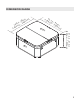
DIMENSION RANGE ) in .4- -mm 8 – 9 ,500 n i .8- m – 2 4 7 m 00 9 (1, a Co ve r 31.4-in – 41.3-in (800-mm – 1,050-mm) Sp 5 35 3.1-i 0-m n – 9 m – 2 2.
OPERATION INSTRUCTIONS To use the Premium Cover Lift, follow the steps below. 13. 13. To Touse usethe theCover CoverCaddy, Caddy,follow followthe thesteps stepsininFig Fig13. 13. 13. To use the Cover Caddy, follow the steps in Fig 13. A) Start with the cover on the spa and the A.A.Cover spa Cover Caddy Coveron onthe the spawith with Cover Caddy Premium Cover Lift in stowed position. stowed A.stowed Cover on the spa with Cover Caddy stowed B) Rotate the arms outward and B.B.
PRODUCT WARRANTY 5-YEAR LIMITED WARRANTY This product (model NP5880) is warranted to the original purchaser to be free from defects in material or workmanship for a period of five (5) years from the date of the original retail purchase. This warranty does not cover defects or damage due to improper installation, alteration, accident, or any other event beyond the control of the manufacturer. Defects or damage resulting from misuse, abuse, or negligence will void this warranty.