
Installation & Assembly


5
EE
CC
BB
GG
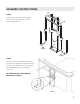
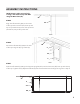
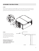
4. Slide the legs of the ccAA Main Unit/ccEE Pivot Arm assembly over the ccGG Support Legs. See
Fig 4.
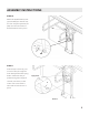
Figure 5
5. Loosely thread the ccE Adjustment Bolt through the ccH Adjustment Bolt Washer and into the threaded
holes in the Support Legs. DO NOT tighten the adjustment screws yet. See Fig 5.
TO CONTINUE WITH BASE MOUNT SETUP, SKIP TO STEP 8
Figure 4
ASSEMBLY INSTRUCTIONS
STEP 3
Slide the legs of the Lift Assembly (AA),
with Pivot Arm (EE) attached, over the
Support Uprights (GG).
STEP 4
Loosely thread the (2) Adjustment Bolts (E)
through the (2) Adjustment Bolt Washers (H)
and into the threaded holes in the Support
Legs. DO NOT tighten the adjustment
screws yet.
TO CONTINUE WITH BASE MOUNT
SETUP, SKIP TO STEP 7.
AA
FF
(Step 8)
(Step 8)
H
E