
Installation & Assembly


6
6. Align the Main Unit assembly in the center of the spa. Line up the Pivot Arm as shown in Fig 6.
Mark the screw holes..
Figure 7
7. Mount the ccAA Main Unit to the side of the spa using the ccZ Lag Bolts. See Fig 7.
Figure 6
SIDE MOUNT ONLY
SIDE MOUNT ONLY
* COVER VALET CANNOT BE HELD RESPONSIBLE FOR THE STRUCTURAL INTEGRITY OF YOUR SPA CABINET
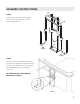
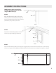
ASSEMBLY INSTRUCTIONS
STEP 5
Align the Lift Assembly (AA) in the center
of the spa with Pivot Arm (EE) lined up with
top of spa. Mark the (4) screw hole positions
(see below) and pre-drill pilot holes.
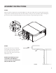
STEP 6
Mount the Lift Assembly (AA) to the side
of the spa using the (4) Lag Screws (Z).
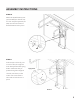
STEP 7
Slide the Lift Assembly (AA) up the Support Uprights (GG) until the Pivot Arm (EE) lines up with the top
of the spa. Tighten the (2) Adjustment Bolts (E) that were threaded into the Support Leg hole in Step 4.
Z
Z
EE
AA
AA
EE
Z
Z
EE
GG
AA
NOTE: Steps 5 and 6 are used only
if using a side mount setup and NOT
using the Base Plate (FF).
E