
Installation & Assembly


8
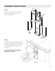
ASSEMBLY INSTRUCTIONS
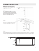
STEP 10
Attach the (2) Ball Studs (L) and
(2) Lock Nuts (K) to the tab and
n. Then snap the Hydraulic Lift
(DD) over the round ends of
the Ball Studs to lock in place.
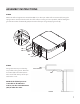
STEP 11
Push the (2) Lock Pins (F), one
on each U-Arm, through the
hole directly behind the spring
button. Make sure the pin
passes through the diagonal
channel (not shown) on the
U-Arm and comes out the
other side to lock the arm in
place.
10. Attach the ccL Ball Studs and ccK Lock Nuts to the Tab and Fin. Then snap the ccDD Gas Shock over the
round ends of the Ball Studs. See Fig 10.
Figure 10
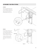
11. Push the ccF Pin through the hole directly underneath the spring button. Make sure the pin passes
through the diagonal channel (not shown) on the U-Arm. See Fig 11.
Figure 11
10. Attach the ccL Ball Studs and ccK Lock Nuts to the Tab and Fin. Then snap the ccDD Gas Shock over the
round ends of the Ball Studs. See Fig 10.
Figure 10
11. Push the ccF Pin through the hole directly underneath the spring button. Make sure the pin passes
through the diagonal channel (not shown) on the U-Arm. See Fig 11.
Figure 11
Spring Button
Fin
Tab
DD
F
K
L