HK 93 Semi Automatic Rifle HK 93 Semi-Automatic Rifle Instruction Manual HECKLER & KOCH, INC. 2148 Pacific Boulevard Sterling, Virginia 20166-8903 U.S.A. TEL. (703) 450-1900 TELEFAX (703) 450-8160 TELEX 7109550846 Heckler & Koch, Inc. U.S.A. WARNING: READ ALL INSTRUCTIONS BEFORE HANDLING & USING THIS FIREARM.
Safety Rules PLEASE READ THIS BEFORE HANDLING YOUR FIREARM. The following safety rules are placed in this manual by Heckler & Koch, Inc. as an important reminder that firearms safety is your responsibility. Firearms can be dangerous and can potentially cause serious injury, damage to property or death, if handled improperly 1. Never point a firearm at anyone, or in any direction other than a safe one, i.e., downrange 2. Always treat all firearms as if they were loaded. 3.
This page left blank intentionally. TABLE OF CONTENTS General……………………………………………………………………… 1 Assemblies…………………………………………………………………. 3 Description of the assemblies……………………………………………. 4 Accessories………………………………………………………………… 9 Handling and operation…………………………………………………… 11 Functioning of parts……………………………………………………….. 14 Stripping the rifle for cleaning…………………………………………….. 15 Reassembling the rifle…………………………………………………….. 17 Adjusting the rotary rear sight…………………………………………….
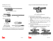
GENERAL This page left blank intentionally. The HK 93 semi-automatic rifle, cal. .223 is a modern small arm produced in accordance with the most advanced manufacturing methods. It permits semi-automatic fire from all positions with the bolt closed. The HK 93 is a recoil operated rifle with stationary barrel and delayed roller locked bolt system. The cartridges are fed either from a 5-round or from a 25-round magazine. Existing models: 1. Rifle with fixed butt stock (Fig. 1) 2.
This page left blank intentionally. 3. Rifle with bipod (Fig. 3 and 3a) 4. Rifle with retractable butt stock (Fig.
ASSEMBLIES (Fig. 6) TECHNICAL DATA 1. Receiver and barrel, cocking mechanism and sights 2. Bolt assembly 3. Grip assembly and trigger mechanism 4. Buttstock 5. Handguard 6. Magazine 7. Accessories (page 9) Caliber………………………………. Range of sight……………………… .223 200, 300, 400 m and open “V” sight Lengths Weapon with fixed butt stock…………………….. Carbine when butt stock retracted………………. Sight radius………………………………………… Barrel……………………………………………….. Twist length………………………………………… 37.00 in. 29.92 in. 19.09 in. 16.14 in.
AIMING ¾ ¾ ¾ ¾ Before aiming, set the sights for the appropriate range and select the aiming point (target). Now aim at the target by means of the diopter hole and the front sight. make sure that the target appears to be resting on top of the front sight post and is properly centered and that there is an even circle of light between the inner circumference of the diopter hole and the outer circumference of the front sight holder.
Assembly 2 Bolt assembly Using the HK 93 Semi-automatic Rifle with Telescopic Sight The bolt assembly consists of: Fig. 8 Bolt assembly Fig. 53 Telescopic sight with mount Fig. 9 Bolt head carrier Fig. 10 Recoil spring guide rod and recoil spring Fig. 11 Bolt head Fig. 12 Locking piece Fig. 13 Firing pin spring Fig. 14. Firing pin The telescopic sight is mounted as follows: ¾ Before attaching, swivel the claws (53/1) on the mount outward.
Assembly 3 Grip assembly and trigger mechanism Carrying and slinging modes, firing positions The grip assembly (Fig. 15) is hinged to the receiver, can be swung down and removed from it. It houses the trigger mechanism (Fig. 16) with hammer, ejector and the safety. The safety axle connects the trigger housing to the grip. Fig. 47 Fig. 48 Fig. 49 Fig. 15 Grip with trigger housing Fig. 50 Fig. 51 Fig. 16 Trigger mechanism and safety Fig.
Assembly 4 Buttstock USING THE COMBAT SLING Fixed buttstock (Fig. 17) The back plate closes the receiver at the rear. It is connected to the receiver by a locking pin and houses the recoil spring, the buffer assembly and the buttstock. The sling holder is attached to the butt stock by two tubular rivets which serve to hold the butt plate and to store the locking pin when stripping the rifle.
Assembly 5 Handguard Windage adjustment ¾ ¾ Point of impact left: Loosen clamping screw (Fig. 43) on top of sight base. Turn adjusting screw (Fig. 44) counter-clockwise according to requirement. Then retighten clamping screw. Point of impact right: Loosen clamping screw (Fig. 43) on top of sight base. Turn adjusting screw (Fig. 44) clockwise according to requirement. Then retighten clamping screw. The detachable handguard (Fig.
ACCESSORIES ADJUSTING THE ROTARY REAR SIGHT Standard carrying sling The standard carrying sling (Fig. 23) is attached to the front of the rifle by snapping its carbine hook into the eye on the front sight holder; at the rear, its loop and spring hook are passed through a fitting in the buttstock. Any corrections which may be necessary when sighting-in, are only performed by adjusting the rear sight for elevation or windage.
REASSEMBLING THE RIFLE ¾ ¾ ¾ ¾ ¾ ¾ ¾ Attach handguard. Insert the assembled bolt with recoil spring into the receiver (locking rollers must rest inside the bolt head.) Attach grip assembly. (Fig. 40) (Set safety lever on grip assembly at “S”). Slide fixed or retractable buttstock onto the receiver and insert locking pins. Hook carrying sling into the eye on the front sight holder. Check the proper reassembly of the rifle by performing several cocking motions.
HANDLING AND OPERATION Filling of magazine One hand holds the magazine (Fig. 27), the other hand puts the cartridge on the magazine lip and presses it under the lip with the thumb. Emptying of magazine One hand holds the magazine. The points of the cartridges point to the front. The second cartridge is pressed down with a small piece of wood or a cartridge, whereby the top cartridge falls out by itself.
SAFETY FEATURES STRIPPING THE RIFLE FOR CLEANING ¾ ¾ ¾ ¾ ¾ ¾ ¾ Engage the safety! Remove magazine. Unload chamber; retract cocking lever and make sure that the chamber is clear. Let cocking lever snap forward. Unhook carrying sling from front sight holder. Remove buttstock locking pin and put it in the tubular rivets in the fixed buttstock. Slide off buttstock and back plate (Fig. 35). Remove grip assembly. Retract bolt assembly by means of the cocking lever and remove it from the receiver (Fig. 37).
Inserting and removing of magazine FUNCTIONING OF PARTS Put at “safe”! The rifle is loaded and the safety set on “F”. By pulling the trigger, the hammer is released and strikes the firing pin which in turn ignites the cartridge. The powder gases drive the bullet out of the barrel. Simultaneously these gases also exert pressure on the cartridge case.