
Operation Manual


HEIDENHAIN MANUALplus 4110 349
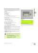
6.16 Undercut Cycles
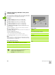
Undercut according to DIN 76 with cylinder
machining G853
The cycle machines the adjoining cylinder, the undercut, and finishes
with the plane surface. It also machines a cylinder start chamfer when
you enter at least one of the parameters "B" or "RB."
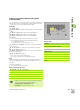
Parameters
FP thread pitch
I undercut diameter (diameter value) (default: Value from standard
table)
K undercut length (default: Value from standard table)
W undercut angle (default: Value from standard table)
R undercut radius (default: Value from standard table)
P oversize
P is not defined: The undercut is machined in one pass
P is defined: Division into pre-turning and finish-turning
– P = longitudinal oversize
– The transverse oversize is preset to 0.1 mm
B cylinder 1st cut length—no input: No chamfer machined at
start of cylinder
RB 1st cut radius—no input: No chamfer radius is machined
WB 1st cut angle (default: 45°)
E reduced feed rate (default: Active feed rate): For the plunge cut
and the thread chamfer
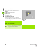
H type of departure (default: 0):
H=0: Tool returns to the starting point
H=1: Tool remains at the end of the plane surface
Note:
Parameters that are not programmed are automatically calculated
from the standard table (see “DIN 76—undercut parameters” on
page 525):
FP from the diameter
I, K, W, and R from FP (thread pitch)
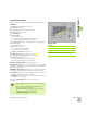
Blocks following the cycle call
Example: G853
%853.nc
[G853]
N1 T21 G95 F0.23 G96 S248 M3
N2 G0 X60 Z2
N3 G853 FP1.5 I47 K15 W30 R2 P1 B5 RB2
WB30 E0.2 H1
N4 G0 X50 Z0
N5 G1 Z-30
N6 G1 X60
N7 G80
END
N.. G853 FP.. I.. K.. W.. /Cycle call
N.. G0 X.. Z.. /Corner point of cylinder start chamfer
N.. G1 Z.. /Undercut corner
N.. G1 X.. /End point of plane surface
N.. G80 /End of contour definition
Undercuts can only be executed in orthogonal, paraxial
contour corners along the longitudinal axis.
Cutting radius compensation: Active.
Oversizes: are not taken into account.