
Operation Manual


HEIDENHAIN MANUALplus 4110 419
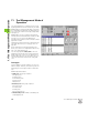
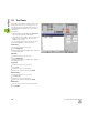
7.4 Tool Data
Lathe tools
Select lathe tools.
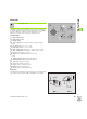
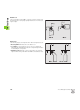
The graphic support window illustrates how goose-necked roughing
and finishing tools for longitudinal machining are dimensioned (WO 1,
3, 5 and 7). On the next page you will find information on the
dimensions of facing tools, neutral tools and button tools.
Tool parameters
X setup dimension in X
Z setup dimension in Z
R cutting radius
WO tool orientation: For code number, see graphic support
window
A tool angle: Range: 0° <= A <= 180°
B point angle: Range: 0° <= B <= 180°
DX wear compensation in X: Range: –100mm < DX < 100mm
DZ wear compensation in Z: Range: –100mm < DZ < 100mm
Q tool text: Reference to tool text
MD direction of rotation—default: Not defined
3: M3
4: M4
TS cutting/spindle speed: default: Not defined
TF feed rate—default: Not defined
PT tool life—default: Not defined
RT: Display field for remaining tool life
PZ quantity—default: Not defined
RZ: Display field for remaining quantity
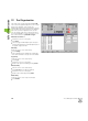
Facing tools
The figure at right explains how to dimension these tools, taking facing
tools with the tool orientations WO=1 and WO=7 as an example.