
User`s manual for cycle programming
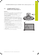


CYLINDER SURFACE (Cycle 27, DIN/ISO: G127, software option 1) 8.2
8
HEIDENHAIN | TNC 640 | User’s manual for cycle programming | 9/2015
233
Cycle parameters
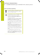
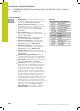
Milling depth Q1 (incremental): Distance between
the cylindrical surface and the floor of the contour.
Input range -99999.9999 to 99999.9999
Finishing allowance for side Q3 (incremental):
Finishing allowance in the plane of the unrolled
cylindrical surface. This allowance is effective in the
direction of the radius compensation. Input range
-99999.9999 to 99999.9999
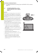
Set-up clearance Q6 (incremental): Distance
between the tool tip and the cylinder surface. Input
range 0 to 99999.9999
Plunging depth Q10 (incremental): Infeed per cut.
Input range -99999.9999 to 99999.9999
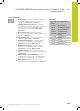
Feed rate for plunging Q11: Traversing speed
of the tool in the spindle axis. Input range 0 to
99999.9999, alternatively FAUTO, FU, FZ
Feed rate for milling Q12: Traversing speed of
the tool in the working plane. Input range 0 to
99999.9999, alternatively FAUTO, FU, FZ
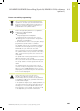
Cylinder radius Q16: Radius of the cylinder on
which the contour is to be machined. Input range 0
to 99999.9999
Dimension type? deg=0 MM/INCH=1 Q17: The
coordinates for the rotary axis of the subprogram
are given either in degrees (0) or in mm/inches (1).
NC blocks
63 CYCL DEF 27 CYLINDER SURFACE
Q1=-8 ;MILLING DEPTH
Q3=+0 ;ALLOWANCE FOR SIDE
Q6=+0 ;SET-UP CLEARANCE
Q10=+3 ;PLUNGING DEPTH
Q11=100 ;FEED RATE FOR
PLNGNG
Q12=350 ;FEED RATE FOR
MILLING
Q16=25 ;RADIUS
Q17=0 ;DIMENSION TYPE