
User`s manual for cycle programming


CONTOUR TURNING INTERPOLATION (Cycle 292, DIN/ISO: G292,
software option 96)
11.6
11
HEIDENHAIN | TNC 640 | User’s manual for cycle programming | 9/2015
301
Defining the tool
Overview
Depending on the setting of the parameter Q560, you can mill
(Q560=0) or turn (Q560=1) the contour. For each of the two
machining modes, there are different possibilities to define the tool
in the tool table. This section describes the different possibilities:
Spindle coupling off, Q560=0
Milling: Define the milling cutter in the tool table as usual by
entering the length, radius, toroid cutter radius, etc.
Spindle coupling on, Q560=1
Turning: The geometry data of the turning tool are converted to
the data of a milling cutter. You now have the following three
possibilities:
Define a turning tool in the tool table (tool.t) as a milling tool
Define a milling tool in the tool table (tool.t) as a milling tool (for
subsequent use as a turning tool)
Define a turning tool in the turning tool table (toolturn.trn)
These three possibilities of defining the tool are described in more
detail below:
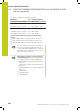
Define a turning tool in the tool table (tool.t) as a milling
tool
If you are working without option 50, define the turning tool
in the tool table (tool.t) as a milling cutter. In this case, the
following data from the tool table are taken into account
(including delta values): Length (L), radius (R) and toroid cutter
radius (R2). Orient the turning tool to the spindle center and
enter this spindle orientation angle in the parameter Q336 of
the cycle. For outside machining, the spindle orientation Q336 is
used; for inside machining, the spindle orientation is calculated
from Q336+180.
The tool holder is not monitored! If the rotation
diameter resulting from the tool holder is greater
than that from the cutting edge, the machine
operator must take this into account for inside
machining.
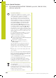
Define a milling tool in the tool table (tool.t) as a milling
tool (for subsequent use as a turning tool)
You can use a milling cutter for interpolation turning. In this
case, the following data from the tool table are taken into
account (including delta values): Length (L), radius (R) and toroid
cutter radius (R2). Orient a cutting edge of the milling cutter to
the spindle center and enter this angle in the parameter Q336.
For outside machining, the spindle orientation Q336 is used;
for inside machining, the spindle orientation is calculated from
Q336+180.
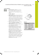
Define a turning tool in the turning tool table (toolturn.trn)
If you are working with option 50, you can define the turning
tool in the turning tool table (toolturn.trn). In this case, the
spindle is oriented to the center of rotation by taking tool-
specific data into account, such as the machining operation
(TO in the turning tool table), the orientation angle (ORI in the
turning tool table) and the parameter Q336.