
User`s manual for cycle programming


Compensating workpiece misalignment by rotating the C axis
(Cycle 405, DIN/ISO: G405)
14.7
14
HEIDENHAIN | TNC 640 | User’s manual for cycle programming | 9/2015
473
14.7 Compensating workpiece
misalignment by rotating the C axis
(Cycle 405, DIN/ISO: G405)
Cycle run
With Touch Probe Cycle 405, you can measure
the angular offset between the positive Y axis of the active
coordinate system and the center of a hole, or
the angular offset between the nominal position and the actual
position of a hole center.
The TNC compensates the determined angular offset by rotating
the C axis. The workpiece can be clamped in any position on the
rotary table, but the Y coordinate of the hole must be positive.
If you measure the angular misalignment of the hole with touch
probe axis Y (horizontal position of the hole), it may be necessary
to execute the cycle more than once because the measuring
strategy causes an inaccuracy of approx. 1% of the misalignment.
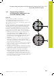
1 Following the positioning logic, the TNC positions the touch
probe at rapid traverse (value from FMAX column) (see
"Executing touch probe cycles", page 454) to touch point 1. The
TNC calculates the touch points from the data in the cycle and
the safety clearance from the SET_UP column of the touch
probe table.
2 Then the touch probe moves to the entered measuring height
and runs the first probing process at the probing feed rate
(column F). The TNC derives the probing direction automatically
from the programmed starting angle.
3 Then the touch probe moves in a circular arc either at measuring
height or at clearance height to the next starting point 2 and
probes the second touch point.
4 The TNC positions the touch probe to starting point 3 and then
to starting point 4 to probe the third and fourth touch points and
positions the touch probe on the hole center measured.
5 Finally the TNC returns the touch probe to the clearance
height and and aligns the workpiece by rotating the table.
The TNC rotates the rotary table so that the hole center after
compensation lies in the direction of the positive Y axis, or on
the nominal position of the hole center—both with a vertical and
horizontal touch probe axis. The measured angular misalignment
is also available in parameter Q150.