
Instruction Manual
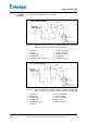
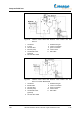
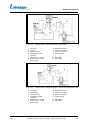
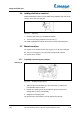
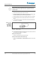
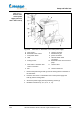
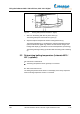
Table Of Contents
- Betriebsanleitung
- 1 Zu diesem Dokument
- 2 Grundlegende Sicherheitshinweise
- 2.1 Allgemeine Sicherheitshinweise
- 2.2 Bestimmungsgemäße Verwendung
- 2.3 Nicht zugelassene Verwendung
- 2.4 Verwendung in explosionsgefährdeten Bereichen
- 2.5 Pflichten des Betreibers
- 2.6 Pflichten des Bedienpersonals
- 2.7 Qualifikation des Personals
- 2.8 Sicherheitsbewusstes Arbeiten
- 2.9 Sicherheitseinrichtungen am Gerät
- 2.10 Schilder am Gerät
- 3 Gerätebeschreibung
- 4 Aufstellung und Inbetriebnahme
- 4.1 Lieferumfang
- 4.2 Transport
- 4.3 Basisgerät aufstellen
- 4.4 Inbetriebnahme
- 4.5 Glassätze montieren
- 4.5.1 Kühlerhalterung installieren (G3–G6)
- 4.5.2 Dampfdurchführung installieren
- 4.5.3 Kühler installieren
- 4.5.4 Vertikalkühler (G3–G6) in Kühlerhalterung befestigen
- 4.5.5 Verdampfungskolben installieren
- 4.5.6 Verdampfungskolbenneigung einstellen
- 4.5.7 Verdampfungskolben-Eintauchtiefe einstellen
- 4.5.8 Verdampfungskolben von Dampfdurchführung lösen
- 4.5.9 Einleitrohr einsetzen
- 4.5.10 Einleitschlauch montieren
- 4.5.11 Auffangkolben montieren
- 4.5.12 Kühlwasser anschließen (außer G5)
- 4.5.13 Vakuum anschließen
- 4.6 Destillationsgut zuführen
- 4.7 Von Hand belüften
- 5 Bedienung Laborota 4000 / 4001 efficient; 4010 / 4011 digital
- 6 Bedienung Laborota 4002 / 4003 control
- 7 Fehler und Fehlerbehebung
- 8 Wartung, Reinigung, Service
- 9 Demontage, Lagerung, Entsorgung
- 10 Zubehör, Ersatzteile
- 11 Anhang
- Instruction manual
- 1 About this document
- 2 Basic safety instructions
- 2.1 General safety instructions
- 2.2 Intended use
- 2.3 Improper use
- 2.4 Use in potentially explosive environments
- 2.5 Responsibilities of the operator
- 2.6 Responsibilities of the operating personnel
- 2.7 Qualifications of the operating personnel
- 2.8 Safety-conscious work
- 2.9 Safety features of the instrument
- 2.10 Labels on instrument
- 3 Description of instrument
- 4 Setup and initial use
- 4.1 Scope of delivery
- 4.2 Transport
- 4.3 Setting up the instrument base
- 4.4 Initial operation
- 4.5 Installing glassware
- 4.5.1 Installing the condenser holder (G3–G6)
- 4.5.2 Installing the vapour tube
- 4.5.3 Installing the condenser
- 4.5.4 Mounting the vertical condenser (G3–G6) to the condenser holder
- 4.5.5 Installing the evaporating flask
- 4.5.6 Adjusting the angle of the evaporating flask
- 4.5.7 Adjusting the immersion depth of the evaporating flask
- 4.5.8 Releasing the evaporating flask from the vapour tube
- 4.5.9 Installing the inlet pipe
- 4.5.10 Installing the inlet hose
- 4.5.11 Installing the receiving flask
- 4.5.12 Connecting cooling water (not G5)
- 4.5.13 Connecting the vacuum
- 4.6 Adding distillation material
- 4.7 Manual aeration
- 5 Using the Laborota 4000 / 4001 efficient; 4010 / 4011 digital
- 6 Using the Laborota 4002 / 4003 control
- 7 Faults and troubleshooting
- 8 Maintenance, cleaning, service
- 9 Disassembly, storage, disposal
- 10 Accessories, spare parts
- 11 Appendix
- Mode d’emploi
- 1 À propos de ce document
- 2 Consignes de sécurité de base
- 2.1 Consignes de sécurité générales
- 2.2 Utilisation conforme
- 2.3 Utilisation non autorisée
- 2.4 Utilisation dans une zone de danger d'explosion
- 2.5 Obligations de l'opérateur
- 2.6 Obligations du personnel opératoire
- 2.7 Qualification du personnel
- 2.8 Utilisation en toute sécurité
- 2.9 Dispositifs de sécurité de l'appareil
- 2.10 Plaques sur l'appareil
- 3 Description des appareils
- 4 Montage et mise en service
- 4.1 Contenu de la livraison
- 4.2 Transport
- 4.3 Montage de l'appareil de base
- 4.4 Mise en service
- 4.5 Montage des jeux de verres
- 4.5.1 Montage du support du refroidisseur (G3–G6)
- 4.5.2 Montage de la traversée de vapeur
- 4.5.3 Montage du refroidisseur
- 4.5.4 Fixer le refroidisseur vertical (G3–G6) sur le support du refroidisseur
- 4.5.5 Montage du ballon évaporateur
- 4.5.6 Régler l'inclinaison du ballon évaporateur
- 4.5.7 Réglage de la profondeur de plongée du ballon évaporateur
- 4.5.8 Retrait du ballon évaporateur de la traversée de vapeur
- 4.5.9 Insertion du robinet d'introduction
- 4.5.10 Montage du tube d'introduction
- 4.5.11 Montage du ballon récepteur
- 4.5.12 Raccordement de l'eau de refroidissement (sauf G5)
- 4.5.13 Raccordement du vide
- 4.6 Ajout de produit de distillation
- 4.7 Ventilation manuelle
- 5 Utilisation des modèles Laborota 4000 / 4001 efficient et 4010 / 4011 digital
- 6 Utilisation du modèle Laborota 4002 / 4003 control
- 6.1 Réglage de la vitesse de rotation
- 6.2 Réglage de la température du bain chauffant
- 6.3 Identification de la température d'ébullition (sur une sonde de température d'ébullition en option)
- 6.4 Réglage du vide
- 6.5 Fonctions temporelles
- 6.6 Gestion des paramètres de distillation
- 6.7 Fonction Ramp
- 6.8 Fonction Auto Start Stop
- 7 Erreurs et résolution des erreurs
- 8 Entretien, nettoyage et service après-vente
- 9 Démontage, stockage et élimination
- 10 Accessoire, pièces de remplacement
- 11 Annexe
- Manual de instrucciones
- 1 Acerca de este documento
- 2 Notas de seguridad básicas
- 2.1 Notas de seguridad generales
- 2.2 Uso previsto
- 2.3 Utilizaciones prohibidas
- 2.4 Utilización en áreas expuestas al riesgo de explosión
- 2.5 Obligaciones de la compañía operadora
- 2.6 Obligación de los operadores del equipo
- 2.7 Cualificación del personal
- 2.8 Trabajar con conciencia de la seguridad
- 2.9 Dispositivos de seguridad del equipo
- 2.10 Placas en el equipo
- 3 Descripción del equipo
- 4 Montaje y puesta en funcionamiento
- 4.1 Contenido del suministro
- 4.2 Transporte
- 4.3 Montar el equipo básico
- 4.4 Puesta en funcionamiento
- 4.5 Montar los juegos de vidrio
- 4.5.1 Instalar el soporte para refrigerante (G3–G6)
- 4.5.2 Instalar el paso de vapor
- 4.5.3 Instalar el refrigerante
- 4.5.4 Fijar el refrigerante vertical (G3–G6) en el soporte para refrigerante
- 4.5.5 Instalar el matraz evaporador
- 4.5.6 Ajustar la inclinación del matraz evaporador
- 4.5.7 Ajustar la profundidad de inmersión del matraz evaporador
- 4.5.8 Separar el matraz evaporador del paso de vapor
- 4.5.9 Colocar el tubo conductor
- 4.5.10 Montar la manguera conductora
- 4.5.11 Montar el matraz receptor
- 4.5.12 Conectar el agua de enfriamiento (excepto G5)
- 4.5.13 Conectar el vacío
- 4.6 Suministrar sustancia de destilación
- 4.7 Ventilación manual
- 5 Manejo Laborota 4000 / 4001 efficient; 4010 / 4011 digital
- 6 Manejo Laborota 4002 / 4003 control
- 6.1 Ajustar el número de revoluciones de rotación
- 6.2 Ajustar la temperatura del baño calefactor
- 6.3 Determinar la temperatura de ebullición (con el sensor de temperatura de ebullición opcional)
- 6.4 Regular el vacío
- 6.5 Funciones de tiempo
- 6.6 Administrar parámetros de destilación
- 6.7 Función Ramp
- 6.8 Función Auto Start Stop
- 7 Fallos y eliminación de fallos
- 8 Mantenimiento, limpieza, servicio técnico
- 9 Desmontaje, almacenamiento, eliminación como residuo
- 10 Accesorios, piezas de repuesto
- 11 Anexo
- Istruzioni per l’uso
- 1 Indicazioni in merito a questo documento
- 2 Indicazioni di sicurezza fondamentali
- 2.1 Indicazioni di sicurezza generali
- 2.2 Utilizzo conforme
- 2.3 Uso non consentito
- 2.4 Utilizzo in aree soggette a rischio di esplosione
- 2.5 Obblighi dell'esercente
- 2.6 Obblighi degli operatori
- 2.7 Qualifica del personale
- 2.8 Consapevolezza nel lavoro
- 2.9 Dispositivi di sicurezza dell'apparecchiatura
- 2.10 Targhette presenti sull'apparecchiatura
- 3 Descrizione dell'apparecchiatura
- 4 Installazione emessa in funzione
- 4.1 Dotazione di fornitura
- 4.2 Trasporto
- 4.3 Installazione strumento base
- 4.4 Messa in funzione
- 4.5 Montaggio dei set vetrerie
- 4.5.1 Installazione supporto refrigerante (G3–G6)
- 4.5.2 Installazione del tubo di passaggio vapore
- 4.5.3 Installazione refrigerante
- 4.5.4 Fissare il refrigerante verticale (G3–G6) nel supporto refrigerante
- 4.5.5 Installazione del pallone di evaporazione
- 4.5.6 Regolazione dell'inclinazione del pallone di evaporazione
- 4.5.7 Regolazione della profondità di immersione del pallone di evaporazione
- 4.5.8 Separare il pallone di evaporazione dal tubo di passaggio vapore
- 4.5.9 Installazione del tubo di immissione
- 4.5.10 Montaggio del tubo flessibile di immissione
- 4.5.11 Montaggio del pallone di raccolta
- 4.5.12 Allacciamento acqua di raffreddamento (tranne G5)
- 4.5.13 Collegamento del vuoto
- 4.6 Apporto di materiale da distillare
- 4.7 Aerazione manuale
- 5 Uso Laborota 4000 / 4001 efficient; 4010 / 4011 digital
- 6 Uso Laborota 4002 / 4003 control
- 6.1 Impostazione del numero di giri di rotazione
- 6.2 Impostazione della temperatura del bagno di riscaldamento
- 6.3 Rilevazione della temperatura di ebollizione (in presenza di un sensore, opzionale, per la temperatura di ebollizione)
- 6.4 Regolazione del vuoto
- 6.5 Funzioni temporali
- 6.6 Gestione dei parametri di distillazione
- 6.7 Funzione Rampa
- 6.8 Funzione Auto Start Stop
- 7 Errori ed eliminazione degli errori
- 8 Manutenzione, pulizia, Servizio Assistenza
- 9 Smontaggio, magazzinaggio, smaltimento
- 10 Accessori, parti di ricambio
- 11 Appendice

Setup and initial use
1.02
Laborota 4000/4001 efficient, 4010/4011 digital, 4002/4003 control 105
Fig. 4-29: VAC senso T / ROTAVAC vario control power supply
A VAC senso T 6 vacuum connector
B ROTAVAC vario control 7 aeration/inert gas
1 main power switch 8 power connection
2 LED 9 Laborota 4002 / 4003
connection
3 locking screws 10 ROTAVAC vario control vacuum
pump
4 VAC senso T / Rotavac vario
control connection
11 vacuum valve
5 bolt 12 vacuum switch box
1.
Remove the positioning screws (3) from the locking tubes on the back of
the instrument.
2. Insert the VAC senso T / ROTAVAC vario control power supply and
bolts (5) into the locking tubes.
3. Secure the power supply with the positioning screws (3).
4. Establish connections (4, 6, 8, 9, 10, 11, 12).
VAC senso T /
Rotavac vario
control power
supply (Laborota
4002 / 4003 control)