
Instruction Manual
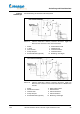
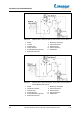
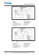
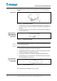
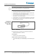
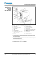
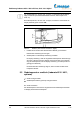
Table Of Contents
- Betriebsanleitung
- 1 Zu diesem Dokument
- 2 Grundlegende Sicherheitshinweise
- 2.1 Allgemeine Sicherheitshinweise
- 2.2 Bestimmungsgemäße Verwendung
- 2.3 Nicht zugelassene Verwendung
- 2.4 Verwendung in explosionsgefährdeten Bereichen
- 2.5 Pflichten des Betreibers
- 2.6 Pflichten des Bedienpersonals
- 2.7 Qualifikation des Personals
- 2.8 Sicherheitsbewusstes Arbeiten
- 2.9 Sicherheitseinrichtungen am Gerät
- 2.10 Schilder am Gerät
- 3 Gerätebeschreibung
- 4 Aufstellung und Inbetriebnahme
- 4.1 Lieferumfang
- 4.2 Transport
- 4.3 Basisgerät aufstellen
- 4.4 Inbetriebnahme
- 4.5 Glassätze montieren
- 4.5.1 Kühlerhalterung installieren (G3–G6)
- 4.5.2 Dampfdurchführung installieren
- 4.5.3 Kühler installieren
- 4.5.4 Vertikalkühler (G3–G6) in Kühlerhalterung befestigen
- 4.5.5 Verdampfungskolben installieren
- 4.5.6 Verdampfungskolbenneigung einstellen
- 4.5.7 Verdampfungskolben-Eintauchtiefe einstellen
- 4.5.8 Verdampfungskolben von Dampfdurchführung lösen
- 4.5.9 Einleitrohr einsetzen
- 4.5.10 Einleitschlauch montieren
- 4.5.11 Auffangkolben montieren
- 4.5.12 Kühlwasser anschließen (außer G5)
- 4.5.13 Vakuum anschließen
- 4.6 Destillationsgut zuführen
- 4.7 Von Hand belüften
- 5 Bedienung Laborota 4000 / 4001 efficient; 4010 / 4011 digital
- 6 Bedienung Laborota 4002 / 4003 control
- 7 Fehler und Fehlerbehebung
- 8 Wartung, Reinigung, Service
- 9 Demontage, Lagerung, Entsorgung
- 10 Zubehör, Ersatzteile
- 11 Anhang
- Instruction manual
- 1 About this document
- 2 Basic safety instructions
- 2.1 General safety instructions
- 2.2 Intended use
- 2.3 Improper use
- 2.4 Use in potentially explosive environments
- 2.5 Responsibilities of the operator
- 2.6 Responsibilities of the operating personnel
- 2.7 Qualifications of the operating personnel
- 2.8 Safety-conscious work
- 2.9 Safety features of the instrument
- 2.10 Labels on instrument
- 3 Description of instrument
- 4 Setup and initial use
- 4.1 Scope of delivery
- 4.2 Transport
- 4.3 Setting up the instrument base
- 4.4 Initial operation
- 4.5 Installing glassware
- 4.5.1 Installing the condenser holder (G3–G6)
- 4.5.2 Installing the vapour tube
- 4.5.3 Installing the condenser
- 4.5.4 Mounting the vertical condenser (G3–G6) to the condenser holder
- 4.5.5 Installing the evaporating flask
- 4.5.6 Adjusting the angle of the evaporating flask
- 4.5.7 Adjusting the immersion depth of the evaporating flask
- 4.5.8 Releasing the evaporating flask from the vapour tube
- 4.5.9 Installing the inlet pipe
- 4.5.10 Installing the inlet hose
- 4.5.11 Installing the receiving flask
- 4.5.12 Connecting cooling water (not G5)
- 4.5.13 Connecting the vacuum
- 4.6 Adding distillation material
- 4.7 Manual aeration
- 5 Using the Laborota 4000 / 4001 efficient; 4010 / 4011 digital
- 6 Using the Laborota 4002 / 4003 control
- 7 Faults and troubleshooting
- 8 Maintenance, cleaning, service
- 9 Disassembly, storage, disposal
- 10 Accessories, spare parts
- 11 Appendix
- Mode d’emploi
- 1 À propos de ce document
- 2 Consignes de sécurité de base
- 2.1 Consignes de sécurité générales
- 2.2 Utilisation conforme
- 2.3 Utilisation non autorisée
- 2.4 Utilisation dans une zone de danger d'explosion
- 2.5 Obligations de l'opérateur
- 2.6 Obligations du personnel opératoire
- 2.7 Qualification du personnel
- 2.8 Utilisation en toute sécurité
- 2.9 Dispositifs de sécurité de l'appareil
- 2.10 Plaques sur l'appareil
- 3 Description des appareils
- 4 Montage et mise en service
- 4.1 Contenu de la livraison
- 4.2 Transport
- 4.3 Montage de l'appareil de base
- 4.4 Mise en service
- 4.5 Montage des jeux de verres
- 4.5.1 Montage du support du refroidisseur (G3–G6)
- 4.5.2 Montage de la traversée de vapeur
- 4.5.3 Montage du refroidisseur
- 4.5.4 Fixer le refroidisseur vertical (G3–G6) sur le support du refroidisseur
- 4.5.5 Montage du ballon évaporateur
- 4.5.6 Régler l'inclinaison du ballon évaporateur
- 4.5.7 Réglage de la profondeur de plongée du ballon évaporateur
- 4.5.8 Retrait du ballon évaporateur de la traversée de vapeur
- 4.5.9 Insertion du robinet d'introduction
- 4.5.10 Montage du tube d'introduction
- 4.5.11 Montage du ballon récepteur
- 4.5.12 Raccordement de l'eau de refroidissement (sauf G5)
- 4.5.13 Raccordement du vide
- 4.6 Ajout de produit de distillation
- 4.7 Ventilation manuelle
- 5 Utilisation des modèles Laborota 4000 / 4001 efficient et 4010 / 4011 digital
- 6 Utilisation du modèle Laborota 4002 / 4003 control
- 6.1 Réglage de la vitesse de rotation
- 6.2 Réglage de la température du bain chauffant
- 6.3 Identification de la température d'ébullition (sur une sonde de température d'ébullition en option)
- 6.4 Réglage du vide
- 6.5 Fonctions temporelles
- 6.6 Gestion des paramètres de distillation
- 6.7 Fonction Ramp
- 6.8 Fonction Auto Start Stop
- 7 Erreurs et résolution des erreurs
- 8 Entretien, nettoyage et service après-vente
- 9 Démontage, stockage et élimination
- 10 Accessoire, pièces de remplacement
- 11 Annexe
- Manual de instrucciones
- 1 Acerca de este documento
- 2 Notas de seguridad básicas
- 2.1 Notas de seguridad generales
- 2.2 Uso previsto
- 2.3 Utilizaciones prohibidas
- 2.4 Utilización en áreas expuestas al riesgo de explosión
- 2.5 Obligaciones de la compañía operadora
- 2.6 Obligación de los operadores del equipo
- 2.7 Cualificación del personal
- 2.8 Trabajar con conciencia de la seguridad
- 2.9 Dispositivos de seguridad del equipo
- 2.10 Placas en el equipo
- 3 Descripción del equipo
- 4 Montaje y puesta en funcionamiento
- 4.1 Contenido del suministro
- 4.2 Transporte
- 4.3 Montar el equipo básico
- 4.4 Puesta en funcionamiento
- 4.5 Montar los juegos de vidrio
- 4.5.1 Instalar el soporte para refrigerante (G3–G6)
- 4.5.2 Instalar el paso de vapor
- 4.5.3 Instalar el refrigerante
- 4.5.4 Fijar el refrigerante vertical (G3–G6) en el soporte para refrigerante
- 4.5.5 Instalar el matraz evaporador
- 4.5.6 Ajustar la inclinación del matraz evaporador
- 4.5.7 Ajustar la profundidad de inmersión del matraz evaporador
- 4.5.8 Separar el matraz evaporador del paso de vapor
- 4.5.9 Colocar el tubo conductor
- 4.5.10 Montar la manguera conductora
- 4.5.11 Montar el matraz receptor
- 4.5.12 Conectar el agua de enfriamiento (excepto G5)
- 4.5.13 Conectar el vacío
- 4.6 Suministrar sustancia de destilación
- 4.7 Ventilación manual
- 5 Manejo Laborota 4000 / 4001 efficient; 4010 / 4011 digital
- 6 Manejo Laborota 4002 / 4003 control
- 6.1 Ajustar el número de revoluciones de rotación
- 6.2 Ajustar la temperatura del baño calefactor
- 6.3 Determinar la temperatura de ebullición (con el sensor de temperatura de ebullición opcional)
- 6.4 Regular el vacío
- 6.5 Funciones de tiempo
- 6.6 Administrar parámetros de destilación
- 6.7 Función Ramp
- 6.8 Función Auto Start Stop
- 7 Fallos y eliminación de fallos
- 8 Mantenimiento, limpieza, servicio técnico
- 9 Desmontaje, almacenamiento, eliminación como residuo
- 10 Accesorios, piezas de repuesto
- 11 Anexo
- Istruzioni per l’uso
- 1 Indicazioni in merito a questo documento
- 2 Indicazioni di sicurezza fondamentali
- 2.1 Indicazioni di sicurezza generali
- 2.2 Utilizzo conforme
- 2.3 Uso non consentito
- 2.4 Utilizzo in aree soggette a rischio di esplosione
- 2.5 Obblighi dell'esercente
- 2.6 Obblighi degli operatori
- 2.7 Qualifica del personale
- 2.8 Consapevolezza nel lavoro
- 2.9 Dispositivi di sicurezza dell'apparecchiatura
- 2.10 Targhette presenti sull'apparecchiatura
- 3 Descrizione dell'apparecchiatura
- 4 Installazione emessa in funzione
- 4.1 Dotazione di fornitura
- 4.2 Trasporto
- 4.3 Installazione strumento base
- 4.4 Messa in funzione
- 4.5 Montaggio dei set vetrerie
- 4.5.1 Installazione supporto refrigerante (G3–G6)
- 4.5.2 Installazione del tubo di passaggio vapore
- 4.5.3 Installazione refrigerante
- 4.5.4 Fissare il refrigerante verticale (G3–G6) nel supporto refrigerante
- 4.5.5 Installazione del pallone di evaporazione
- 4.5.6 Regolazione dell'inclinazione del pallone di evaporazione
- 4.5.7 Regolazione della profondità di immersione del pallone di evaporazione
- 4.5.8 Separare il pallone di evaporazione dal tubo di passaggio vapore
- 4.5.9 Installazione del tubo di immissione
- 4.5.10 Montaggio del tubo flessibile di immissione
- 4.5.11 Montaggio del pallone di raccolta
- 4.5.12 Allacciamento acqua di raffreddamento (tranne G5)
- 4.5.13 Collegamento del vuoto
- 4.6 Apporto di materiale da distillare
- 4.7 Aerazione manuale
- 5 Uso Laborota 4000 / 4001 efficient; 4010 / 4011 digital
- 6 Uso Laborota 4002 / 4003 control
- 6.1 Impostazione del numero di giri di rotazione
- 6.2 Impostazione della temperatura del bagno di riscaldamento
- 6.3 Rilevazione della temperatura di ebollizione (in presenza di un sensore, opzionale, per la temperatura di ebollizione)
- 6.4 Regolazione del vuoto
- 6.5 Funzioni temporali
- 6.6 Gestione dei parametri di distillazione
- 6.7 Funzione Rampa
- 6.8 Funzione Auto Start Stop
- 7 Errori ed eliminazione degli errori
- 8 Manutenzione, pulizia, Servizio Assistenza
- 9 Smontaggio, magazzinaggio, smaltimento
- 10 Accessori, parti di ricambio
- 11 Appendice

Aufstellung und Inbetriebnahme
1.02
Laborota 4000/4001 efficient, 4010/4011 digital, 4002/4003 control 29
Schlauchführung der einzelnen Vakuumsysteme
Bild 4-17: Laborota 4000/4001 efficient, Laborota 4010/4011 digital mit
Rotavac valve control und Vac control automatic
1 Kühler 6 Kabel Vakuumventil
2 Y-Stück 7 Netzanschluss
3 Vakuumventil 8 Vakuumanschluss
4 Pumpe Auspuff 9 Vakuumschlauch
5 Kondensatkühler (optional) 10 Belüftung / Schutzgas
Bild 4-18: Laborota 4000/4001 efficient, Laborota 4010/4011 digital mit
Rotavac valve control und Vac control automatic und Woulff’scher
Flasche
1 Kühler 6 Kabel Vakuumventil
2 Woulff’sche Flasche 7 Netzanschluss
3 Vakuumventil 8 Vakuumanschluss
4 Pumpe Auspuff 9 Vakuumschlauch
5 Kondensatkühler (optional) 10 Belüftung / Schutzgas
Vakuum-
verbindungen