page 1 of 34 ROTAVAC vario tec ROTAVAC vario control Instruction manual Documents are only to be used and distributed completely and unchanged. It is strictly the users´ responsibility to check carefully the validity of this document with respect to his product. Manual-no.
page 2 of 34 Documents are only to be used and distributed completely and unchanged. It is strictly the users´ responsibility to check carefully the validity of this document with respect to his product. Manual-no.
page 3 of 34 [GB] It is imperative to read this instruction manual prior to initial operation! Comply with safety instructions! Keep for further use! This documentation is not subject to revision service! Documents are only to be used and distributed completely and unchanged. It is strictly the users´ responsibility to check carefully the validity of this document with respect to his product. Manual-no.
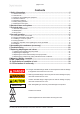
page 4 of 34 Contents 1 Safety information....................................................................................................5 1.1 General information.......................................................................................................................5 1.2 Intended use..................................................................................................................................5 1.3 Setting up and installing the equipment..............................
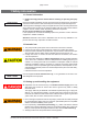
page 5 of 34 1 Safety information 1.1 General information NOTICE ☞ Read and comply with this manual before installing or operating the equipment. Remove all packing material, remove the product from its packing-box, remove the protective covers from the inlet and outlet ports and keep, inspect the equipment. If the equipment is damaged, notify the supplier and the carrier in writing within three days; state the item number of the product together with the order number and the supplier’s invoice number.
page 6 of 34 ☞ Ensure that the coolant outlet pipeline of the condenser (accessory) is always free and that it cannot get blocked. Install an optional coolant valve always in the supply line of the exhaust waste vapor condenser only. ☞ Secure coolant hoses at the hose nozzles (e.g. with hose clip) to prevent their accidental slipping. ☞ Check the overpressure safety relief device at the exhaust waste vapor condenser in appropriate intervals.
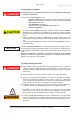
page 7 of 34 1.5 Operating conditions ➨ The pumps have no approval for operation in or for pumping of potentially explosive atmospheres. ➨ The pumps are not suitable to pump - unstable substances and substances which react explosively under impact (mechanical stress) and/or when being exposed to elevated temperatures without air, - self inflammable substances, - substances which are inflammable without air and - explosive substances.
page 8 of 34 • Comply with applicable regulations when disposing of chemicals. Take into consideration that chemicals may be polluted. Take adequate precautions to protect people from the effects of dangerous substances (chemicals, thermal decomposition products of fluoroelastomers), wear appropriate safety-clothing and safety glasses. • Use only genuine spare parts and accessories.
page 9 of 34 1.7 Maintenance and repair NOTICE Wear parts have to be replaced regularly. In case of normal wear the lifetime of the diaphragms and valves is > 10000 operating hours. Bearings have a typical durability of 40000 h (see section 7 ”Replacing diaphragms and valves”). ➨ Isolate equipment from mains and wait two minutes before starting maintenance to allow the capacitors to discharge. ☞ Ensure that the pump cannot be operated accidentally.
page 10 of 34 2 Standard items and options Item or qty P/N 230/240 V 50/60 Hz P/N 115 V 50/60 Hz ROTAVAC vario control (pump) 1 591-00141-00 591-00141-01 ROTAVAC vario tec (pump) 1 591-00171-00 591-00171-01 Standard items ROTAVAC vario control / ROTAVAC vario tec ROTAVAC vario control (pump) 1 ROTAVAC vario tec (pump) 1 Power cord 1 Instruction manual 1 01-005-004-90 Warranty card / Confirmation of condition of unit 1 01-006-002-58 14-007-003-81 14-007-003-89 Accessories (option
page 11 of 34 3 Technical data Type ROTAVAC vario tec ROTAVAC vario control Maximum pumping speed m3/h 1.0 1.
page 12 of 34 3.1 Gas inlet temperatures Operating condition Inlet pressure Permitted range of gas temperatures at inlet Continuous operation > 100 mbar (high gas load) +10°C to +40°C Continuous operation < 100 mbar (low gas load) 0°C to +60°C Short-time (< 5 minutes) < 100 mbar (low gas load) -10°C to +80°C 3.
page 13 of 34 ROTAVAC vario tec 3 4 6 7 5 2 1 ROTAVAC vario control 3 4 6 7 5 2 1 Documents are only to be used and distributed completely and unchanged. It is strictly the users´ responsibility to check carefully the validity of this document with respect to his product. Manual-no.
page 14 of 34 ROTAVAC vario control with exhaust waste vapor condenser (accessory) 8 5 11 10 3 4 6 7 12 2 1 13 9 Documents are only to be used and distributed completely and unchanged. It is strictly the users´ responsibility to check carefully the validity of this document with respect to his product. Manual-no.
page 15 of 34 4 Use and operation 4.1 Connection of the control cable Factory-set, the pump is designed for operation with a control signal; i.e. without a control signal, the pump does not start! Connect the control cable of the pump to the vacuum box (see instruction manual Hei-VAP Precision). 4.
page 16 of 34 NOTICE Avoid throttling losses by using connecting pipes with large diameter and keeping them as short as possible. Install outlet pipelines always falling to avoid backflow of condensate towards the pump. Use of a suitable valve to isolate the pump from the vacuum system is recommended to allow the pump to warm up before pumping condensable vapors or to clean the pump before it is switched off. When assembling, ensure vacuum-tightness. After assembly, check the whole system for leaks.
page 17 of 34 • • • • • • • • The gas outlet (hose nozzle 10 mm) must not be blocked. The exhaust pipeline has always to be free and pressureless to enable an unhindered discharge of gases. If necessary connect the exhaust to a suitable treatment plant to prevent the discharge of dangerous gases and vapors to the surrounding atmosphere. Attention: Install hoses of the cooling system in a way to avoid flow / dropping of condensed water onto the pumping unit (especially cables and electronic parts).
page 18 of 34 4.5 Attention: Important notes regarding the use of gas ballast ➨ When using air rather than inert gas, risk of significant damage to equipment and/ or facilities, risk of personal injury or even loss of life exists due to the formation of hazardous and/or explosive mixtures if air and pumped media react inside or at the outlet of the pump. ➨ Make sure that air/gas inlet through the gas ballast valve never leads to hazardous, explosive or otherwise dangerous mixtures.
page 19 of 34 NOTICE Do not allow the catchpot to get overfilled. Maximum liquid level approx. 80% to avoid problems when removing the catchpot. Check liquid level in the catchpot regularly and drain catchpot in time. Permissible range of coolant temperature at the exhaust waste vapor condenser: -15°C to +20°C. Check hose connections prior to starting operation of the cooling system. Check coolant hoses regularly during operation.
page 20 of 34 5 Assembling the condenser (accessory) ➨ Unscrew the hose nozzle at the outlet of the pump using an open-ended wrench. ➨ Unscrew cover. ➨ Unscrew both square nuts at the mounting angle and remove screws. ➨ Feed the two square nuts into the groove at the upper side of the housing cover. ➨ Assemble cover. Documents are only to be used and distributed completely and unchanged.
page 21 of 34 ➨ Screw hose connection of the exhaust waste vapor condenser to the outlet of the pump using an open-ended wrench. ☞ Align the square of the hose connection so that the mounting angle for the condenser can be assembled (see figure). ➨ Remove catchpot at the condenser. ➨ Loosen the union nut at the inlet of the condenser. ➨ Slide the mounting angle onto the housing cover of the pump as far as it will go (over the square of the hose connection).
page 22 of 34 6 Troubleshooting Fault Possible cause Remedy ❑ ➨ Supply voltage too low or power supply failure? ✔ ➨ Control signal for motor speed ✔ is missing? Check control signal. ➨ Pressure in outlet pipeline too ✔ high? Remove blockade in line, open valve. ➨ Motor overloaded? ✔ Allow motor to cool down, identify and eliminate cause of failure. Manual reset is necessary. Switch off pump or unplug mains.
page 23 of 34 7 Replacing diaphragms and valves ☞ Before starting maintenance isolate the pump from the electrical supply and wait two minutes after isolating the equipment from mains to allow the capacitors to discharge. Avoid the release of pollutants. Allow sufficient cooling of the pump. ☞ Ensure that the pump cannot be operated accidentally. Never operate the pump if covers or other parts of the pump are disassembled. Never operate a defective or damaged pump.
page 24 of 34 Tools required (metric): - diaphragm key w/f 46 (enclosed in the set of seals) open ended wrench w/f 14 / 17 hex key size 4 ☞ Please read section ”Replacing diaphragms and valves” completely before starting maintenance. Partially the pictures show pumps in other versions. This doesn’t influence replacing diaphragms and valves of the pump. 7.1 Cleaning and inspecting the pump heads ➨ Use open-ended wrench (w/f 17) to loosen the union nut at the hose connection next to the gas ballast.
page 25 of 34 ➨ Take the head covers carefully off the housing to check the valves. Note the position of the valves and remove them. ☞ Replace valves if damaged. Use petroleum ether or industrial solvent to remove deposits. Do not inhale. ➨ Check the diaphragms for damage and replace if necessary.
page 26 of 34 7.2 Replacing the diaphragm ➨ Lift diaphragm carefully. ➨ Apply pressure to the adjacent clamping disc to bring connecting rod into upper turning point position if necessary. ☞ Never use a spiky or sharp-edged tool to lift the diaphragm. ➨ Use the diaphragm key to grip the diaphragm support disc below the diaphragm. ➨ Apply pressure to the diaphragm clamping disc to bring the diaphragm into the lower turning point position.
page 27 of 34 ➨ Bring the diaphragms into a position in which they are in contact with the housing and centred with respect to the bore. ➨ Lay pump down and support appropriately. ➨ Assemble head covers and valves. ☞ Check for correct position (see also fig. below).
page 28 of 34 ➨ Position housing cover. ☞ Move housing cover slightly to make sure that the head covers are correctly positioned. ➨ Screw in the six socket head screws fixing the housing cover crosswise first slightly, then tighten. ☞ Do not tighten until head cover is in contact with housing, max. torque 6 Nm. Replace diaphragms and valves similarly on the other side of the pump (only ROTAVAC vario control). ➨ Use open ended wrench (w/f 14) to reconnect hose to elbow fitting.
page 29 of 34 7.4 Replacing the overpressure safety relief device at the condenser Overpressure safety relief device......................................... ........................................................................ 23-30-01-04-98 Round bottom flask 500 ml, coated............... 514-83000-02 ➨ Remove joint clip at the catchpot. ➨ Unscrew the four Torx screws at the counter holder of the condenser and remove condenser. Thereby remove the adapter from the inlet of the condenser.
page 30 of 34 8 Warranty, liability, copyright Warranty Heidolph Instruments provides a three-year warranty on the products described here (with the exception of glass and consumable parts) if registered with enclosed warranty card or via internet (www.heidolph. com). Warranty starts with the date of registration. Without registration warranty starts according to serial number. This warranty covers defects in materials and workmanship. Transit damage is excluded from this warranty.
page 31 of 34 9 FAQ / repair work If any aspect of installation, operation or maintenance remains unanswered in the present manual, please contact the following address. For repair services please call Heidolph Instruments or your local, authorized Heidolph Instruments Dealer. Note: You will receive approval for sending your defective item to the following address: Heidolph Instruments GmbH & Co. KG Lab Equipment Sales Walpersdorfer Str.
page 32 of 34 10 Confirmation of condition of unit In case of repair 1. Details about the unit Model _________________________ Serial number _________________________ Reason for repair _________________________ 2. Has the unit been cleaned or decontaminated / sterilized? yes no 3.
page 33 of 34 11 CE Declaration of conformity Documents are only to be used and distributed completely and unchanged. It is strictly the users´ responsibility to check carefully the validity of this document with respect to his product. Manual-no.
page 34 of 34 Disclaimer: Our technical literature is only intended to inform our customer. The validity of general empirical values and results obtained under test conditions for specific applications depend on a number of factors beyond our control. It is therefore strictly the users´ responsibility to very carefully check the validity of application to their specific requirements. No claims arising from the information provided in this literature will, consequently, be entertained.