
Owner manual


Documents are only to be used and distributed completely and unchanged. It is strictly the users´ responsibility to check carefully
the validity of this document with respect to his product. Manual-no.: 999223 / 08/07/2009
page 16 of 34
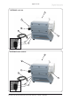
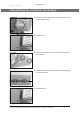
Catchpot:
The round bottom ask is coated with a protective layer to
prevent disintegration in case of breakage or implosion.
➨ Assemble the catchpot using the joint clip.
overpres-
sure safety
relief de-
vice
catchpot at
the outlet
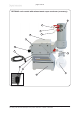
Exhaust waste vapor condenser (accessory)
Exhaust waste vapor condenser:
➨ Assemble hose nozzles for coolant inlet (1) and coolant
outlet (2) pipelines at the exhaust waste vapor conden-
ser.
The exhaust waste vapor condenser enables an efcient
condensation of the pumped vapors at the outlet.
☞ Nobackowofcondensates.
☞ Controlled recovery of condensates.
☞ Nextto100%solventrecovery.
☞ The isolation cover protects against glass splinters in case
of breaking, acts as thermal isolation to avoid condensa-
tion of humidity and is intended to absorb shocks.
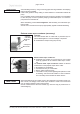
Attach the pipelines of the coolant circuit to the respective hose nozzles (hose noz-
zles 6-8 mm, see image) at the waste vapor condenser. Check hose connections
prior to starting operation of the cooling system.
Secure coolant hoses at the hose nozzles (e.g. with hose clip) to prevent their ac-
cidental slipping.
(2)
outlet (gas!; hose nozzle 10 mm)
(1)
Avoid throttling losses by using connecting pipes with large diameter and keeping
them as short as possible.
Install outlet pipelines always falling to avoid backow of condensate towards the
pump.
Use of a suitable valve to isolate the pump from the vacuum system is recommended
to allow the pump to warm up before pumping condensable vapors or to clean the
pump before it is switched off.
When assembling, ensure vacuum-tightness. After assembly, check the whole sys-
tem for leaks.
Secure hose connections at the pump appropriately against accidental detaching.
NOTICE
NOTICE