
User Manual

194-2000-1001
07/12
Control Arm Installation:
1. Park your vehicle on level ground. Block the rear tires of the
vehicle so the vehicle is stable and cannot roll. Safely lift the front of
the vehicle and support the axel with jack stands. Place jack stands
securely on both the driver and the passenger sides of the axel.
Remove the wheels from both sides.
NOTE: If you are ONLY replacing the upper control arms, you may not
need to remove the lower arms. If that's the case, you can skip step 2.
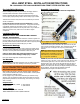
2. Remove lower
arm control arm
bolt. NOTE: Please
refer to installation
instructions for the
HBS adjustable
Lower Control
Arms or reference
your OEM manual
as a guide. If you
intend to retain
and re-use the cam bolt, place a line on the washer and frame with
chalk or marker to indicate the position of the cam bolt for
reinstallation later. Remove the front cam bolt. Remove rear mounting
bolt. This will release the lower arm completely.
3. Remove upper control arm. Remove both forward and rear
14mm mounting bolts. This will release the upper control arm so it
can be removed.
4. Insert new upper control arm in existing mounts. Ensure the
left-hand threaded joint (silver nut) is toward the rear of the vehicle
and the right-hand threaded joint (gold nut) is toward the front. Install
the rear joint first using the new HBS-provided 14mm X 150mm
hardware with the washer on the bolt head and the nut toward the
outside of the vehicle. Do not torque, finger tighten only. Repeat for
forward mounting bolt using the new HBS-provided 14mm X 100mm
hardware.
5. Refer to the instructions for installing the new lower control
arm in existing mounts. Follow the installation steps provided with
the HBS Adjustable Lower Control Arms.
6. Torque fasteners. Torque each fastener to specification.
7. Repeat steps 1 through 6 on the opposite side of the vehicle.
Control Arm Adjustment:
1. To adjust the arms: Park your vehicle on level ground. On your
new arms, rotate the center link so the arms are at their shortest
possible length. Begin rotating each arm (driver's side and passenger's
side) THE SAME NUMBER OF TURNS until the bottom of the shocks
are just forward of the top of the shock. There is no standard number
of turns that will accomplish this. Each truck may require a different
number of rotations to reach the proper position.
IMPORTANT: The number of rotations of the control arms should be
the same for both the driver's and passenger's side of the vehicle. This
is especially important if you are re-using your OEM cam bolts. If you
are replacing your cam bolts with the HBS CBE kit, your alignment
shop may adjust the rotation of each arm to achieve perfect alignment.
However, for your safety and the safety of your vehicle, have your
truck aligned immediately.
The HBS Adjustable
Control Arms have up
to 2" of adjustment
designed into them. It
is important to avoid
extending the length
beyond the designed
amount of adjustment.
UNDER NO CIRCUMSTANCES should the arms be adjusted
beyond the point where more than 1" of joint threads are
exposed! Extending the arms further can lead to critical
failure that could result in vehicle damage, personal injury,
and even death. Any adjustment beyond 1" of exposed
threads will void all warranties.
2. Have the vehicle aligned. It is necessary to apply thread-lock
to the jam nuts of each end joint of the new control arms to ensure
the nuts maintain position over time. However, once the thread lock
cures, you should never adjust the arms without cleaning off the old
thread lock and applying a new solution. It is required that the
vehicle be aligned before applying the thread lock for this reason.
3. Apply thread-lock. Once the adjustment has been reached and
the vehicle has been properly aligned, apply thread-lock.
When applying the thread lock you will want to ensure the solution
gets onto the threads that fit inside the center link as well as the jam
nut. Make a mark across the jam nuts onto the center link. You will
use this mark to ensure you return the parts to the same location.
Loosen the jam nuts. Record the number of turns you loosen the
nuts below. Then adjust the center link out, exposing more threads,
Record the number of turns below.
Driver's side: Passenger's side:_________
Front nut: __________ Front nut: __________
Rear nut: __________ Rear nut: __________
Center link: ________ Center link: ________
Generously apply the thread lock onto the exposed threads. Return
the center link and jam nuts to their previous location. The handling
cure time for the thread lock is 10-12 minutes. You will need to
tighten the jam nuts within that time frame. Full cure time is 24
hours.
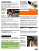
9. Tighten the jam nuts. Put 1-1/2” wrench over the flat sections
on the center link to
keep it from twisting,
then place 1-7/8”
wrench onto the nut.
You will want to ensure
that the joints are
parallel within the
mounts, not twisted or
binding while you are
tightening the nuts. If
you are using wrenches
purchased from Hell
Bent Steel, do not use
more than 16-inch
cheater bar on either wrench.