
User Manual


Date: 2011-11-04
No.:
Hella KGaA
Hueck & Co.
59552 Lippstadt
Subject:
LCA (Lane Change Assist), Gen. 1.7
SWA (Spurwechselassistent), Gen. 1.7
Page 4 of 5
Signed by: Checked by:
Hella 3399DE (2000
-05)
Vertraulich. Weitergabe sowie Verwertung und Mitteilung des Inhalts ist nur mit unserer ausdrücklichen Genehmigung gestattet. Alle Rechte vorbehalten.
The RF units each consist of
• one 24-GHz-VCO,
• one transmit antenna,
• two receivers (each consisting of antenna, LNA, mixer, BPF and base-band amplifier) and
• one 2.4-GHz-PLL oscillator with a 10x-frequency multiplier.
The transmit signal is generated by the 24-GHz-VCO.
The 24-GHz-VCO is frequency modulated by a DAC on the DSP-board.
The DSP-board is able to switch off the transmitter.
The tenth harmonic of 2.4-GHz-PLL is generated and used to align the modulation of the 24-GHz-VCO
and to keep it within the frequency band limits.
The transmit antenna pattern is a microstrip patch antenna array with 5x8 elements.
It is designed to illuminate the rear and the side of the vehicle and is thus a medium gain antenna.
The three receivers down-convert the receive signals directly to zero-IF by using the 24-GHz-VCO
signal.
The base-band receiver signals are digitized by ADCs on the DSP-board.
The receiver antennas are microstrip patch antennas with a lower gain than the transmit antenna (1x8 or
2x8 elements).
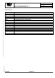
Technical Data of LCA
Supply Voltage +9 V … +15 V
Supply Current appr. 0.5 A (of master and slave without lamps connected)
Frequency Band 1 24075 MHz ... 24175 MHz
Frequency Band 2 24150 MHz … 24250 MHz
Modulation FMCW
Modulation Bandwidth < 100 MHz
EIRP < +20 dBmW
Antenna Type microstrip patch array
Antenna gain 16 dBi
Operating Temperature Range -40°C …+70°C
Storage Temperature Range -40°C …+90°C
Supply Voltage +9 V … +15 V