Operator‘s Manual MMS® Inspection DFT Gage type High Coating Thickness Material Analysis Nanoindentation Material Testing
MMS® Inspection DFT Gage type High Instruments for coating thickness measurements Document no. 902-624 Issue date 2019-09-09 (for software version 1.0.0+3) Manufacturer Helmut Fischer GmbH Phone: Institut für Elektronik und Messtechnik Fax: +49 (0) 70 31 3 03 - 0 +49 (0) 70 31 3 03 - 710 Industriestraße 21 www.helmut-fischer.com D-71069 Sindelfingen mail@helmut-fischer.com On our home page www.helmut-fischer.
1 Safety information . . . . . . . . . . . . . . . . . . . . . . . . . . . . . . . . . . 1 1.1 1.2 1.3 2 Description . . . . . . . . . . . . . . . . . . . . . . . . . . . . . . . . . . . . . . . . 3 2.1 2.2 2.3 2.4 2.5 2.6 3 5 .. .. .. .. .. .. . . . . . . .. .. .. .. .. .. . . . . . . .. .. .. .. .. .. . . . . . . .. .. .. .. .. .. . . . . . . . . . . . . 3 4 5 6 8 9 Installing batteries . . . . . . . . . . . . . . . . . . . . . . . . . . . . . . 17 Switching on the gage . . . . . . . . . .
9 Glossary . . . . . . . . . . . . . . . . . . . . . . . . . . . . . . . . . . . . . . . . . 40 9.1 9.2 Glossary - Display symbols . . . . . . . . . . . . . . . . . . . . . . . . 43 Glossary - Display texts. . . . . . . . . . . . . . . . . . . . . . . . . . . 44 10 About . . . . . . . . . . . . . . . . . . . . . . . . . . . . . . . . . . . . . . . . . . . 47 11 Legal Informations . . . . . . . . . . . . . . . . . . . . . . . . . . . . . . . . . . 48 11.1 USA, FCC (Federal Communications Commission) . . .
Safety information If you use the instrument as intended and observe the safety information, the instrument poses no danger. Please read and follow this Operator's Manual and observe the safety information. Also observe generally applicable safety and accident prevention regulations. 1.1 Intended use The gage is intended solely for measurement of coating thicknesses. Only accessories approved or recommended by the manufacturer may be connected to the gage. Any use beyond this is not the intended use.
Safety information Potentially explosive environment The gage and accessories are not suitable for use in potentially posted environments. ► Operate the gage and accessories only outside of potentially explosive areas! 1.3 Safety of the electrical equipment Only accessories approved or recommended by the manufacturer may be connected to the gage! USB cable Damaged USB cable Kinking or pinching the USB cable can result in a broken wire. Data transmission is then no longer possible.
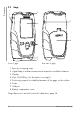
Description The gages in the MMS Inspection DFT series measure coating thicknesses easily, quickly and in a nondestructive manner. Gage construction with an integrated measuring probe allows single-hand measurements, preferably on flat and cylindrical samples.
Description 2.
Keys Description 2.3 There are 4 keys for operating the gage. The bottom line of the display always shows the functions of the 4 keys (see illustration below). The assignment depends on the opened menu page. SEL The function shown on the display is assigned to the key directly underneath (example).
Description 2.
Rename Rename a selected calibration Quick Activate a semi-automatic calibration routine Reset Delete all coating thickness correction values from the selected calibration Delete Delete a selected calibration Gage Settings > Language Select the display language Display Settings > Brightness Flip Display Indication Settings > Key press signal Audible signal Optical Indication Vibration Connections > USB Mode WiFi Date & Time > More Settings > Units (for new b atches) Default Value Resolutio
Description 2.5 Gage concept In order to measure, a Batch (file) and a suitable Calibration (reference) must be created in the gage for the Measuring application. A description of the terms measuring application, batch and calibration can be found in Chapter "Glossary".
Data Sheet MMS® Inspection DFT Coating Thickness Measurement on Virtually all Metals Non-destructive measurements Universal applicable coating thickness gage 1.
MMS® Inspection DFT Description The gage models MMS Inspection DFT measure coating thicknesses easily, quickly, non-destructively and with the precision that is typical for all Fischer instruments.
MMS® Inspection DFT Batch Template Packages Templates for Creation Measurement Tasks Only available for gage variant High The packages contain various batch types. That are batch templates with especially designed measurement tasks for specific coating thickness measurement applications.
MMS® Inspection DFT Metrological Standard Functions Measurement Tasks Measurement reading storage On/Off switchable Measurement units µm/mm or mils/inches Measurement modes Single reading mode After each placing of the gage probe the measuring reading is displayed and stored automatically. Free running mode After placing the gage probe the continuous display of the measured readings appears without automatic storage. Useful for quick checking of coating thicknesses over a defined surface area, e.g.
MMS® Inspection DFT General Features Test methods Gage type FE and FE+NF • Magnetic induction method (ISO 2178, ASTM D7091, measurement of non-magnetic coatings on magnetic substrates) Gage type FE+NF • Eddy current method (ISO 2360, ASTM D7091, measurement of non-conductive coatings on non-magnetic substrate metals) Automatic selection of the test method corresponding to the base material Factory Calibration Each individual gage is factory calibrated at several reference points with the greatest care
MMS® Inspection DFT General Features USB port 2.0 Type C • For service purpose • For connection to PC for data transfer, max. cable length: 3 m (118 inches) Wireless interface Only available in the variants High Admissible climatic conditions during operation Surface temperature WiFi: WiFi module integrated in gage, Standards IEEE 802.11b/g/n Bluetooth: Bluetooth module integrated in gage, Bluetooth v4.
MMS® Inspection DFT * The following specifications are valid for measurements by using the Single reading measurement mode Measurement Ranges* The values for measurement range, trueness, repeatability precision and measurement errors are valid for electrically non-conductive coating materials on steel or iron (NC/FE). The values may differ for measurements on non-ferrous coating materials (NF). Steel, iron, cast iron base materials (FE) Non-ferrous metal base materials (NF) 0 … 2500 µm (98.
MMS® Inspection DFT Influence* Non-ferrous metal base materials (NF) Steel, iron, cast iron base materials (FE) The following values are valid for a coating thickness with a nominal value of 75 µm / 2.95 mils. The quantity of influences are stated with the expanded measurement uncertainty U with the expanded factor of k = 2 (defines an interval with the confidence level of 95.45 %) - according to ISO/IEC Guide 98-3:2008-09 "Guide to the expression of uncertainty in measurement".
3.1 Setup Installing batteries Setup 3 3.2 Switching on the gage ► Press the 1 s. key for approx. The main menu appears in the display or the measurement view for the batch that was open at shutdown. 3.3 Battery polarity Observe the correct polarity when inserting the batteries! Damage to the instrument The use of defective batteries or the wrong type of battery causes damage to the gage. Leaking batteries destroy the gage's electronics. ► Use only undamaged batteries.
Getting started 4 Getting started All the settings relevant to measuring the coating thickness of a coated sample 1 and the measurement readings themselves are saved in a file. Such a file is called a batch. In the batch, you define the measurement procedure, e.g. whether the specification limits are to be monitored during the measurement or whether the measurement readings are to be grouped in measurement block. In addition, you must assign a calibration (reference) to the batch in order to measure.
Settings for measurement In order to measure, you need to create and open a Batch (measuring application file). In a batch, you define the Measuring application and settings for the measurement procedure, e.g. whether the specification limits are to be monitored during the measurement or whether the measurement readings are to be grouped in measurement block. The link to the Calibration to which the measurements are referenced is also saved in the batch file.
Settings for measurement 5.1 Creating a new batch A Batch is created by selecting a Batch type. Each batch type is assigned a certain Calibration method and contains presets for the measurement process. Calibration and setup routines simplify creation of a batch. Selection of the batch type and the associated calibration method is based on the requirements of the guideline/standard or the accuracy of measurement needed. An overview and description of the available batch types can be found on page 11.
This completes the creation process for a new batch. What you can do next • Measure, see Page 23 • Assign a different calibration to the batch, see page 22 5.2 Opening a batch Before you start • The gage is switched on ( key) Opening an existing batch 1. Main Menu () > Batches 2. Select the desired batch from the list: 3. Tap on OK, to confirm your selection 4.
Settings for measurement 5.3 Assigning a different calibration to the opened batch Before you start • The gage is switched on ( key) • The desired batch is opened, the corresponding batch name appears in the colored header field Assigning a new calibration 1. ‘Main Menu () > Batch Modify > OK > More Settings > OK > Calibration Assign > OK 2. Select an existing calibration from the list: Only the calibrations whose calibration method matches the open batch are displayed. 3.
Measurement During the measurement you can also: • Delete single readings: Press the key • View the statistics of the open measurement block: Press the BLOCK key 6.1 Notes on coating thickness measurement Essentially: If the specified precision is not achieved during the measurement, you must recalibrate the probe, see page 25. Measured readings outside the specified tolerance limits are displayed in red and indicated by an illuminated red LED.
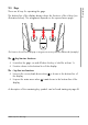
Measurement 6.3 Measuring - Procedure 1 Place the gage Place the gage on the coated sample. NF/FE Batch 03 (IDV) 125 115 No X Min 120 1 121 118 n s Max 2 Measurement acquisition An audible signal as well as the lighting of the signal lamp reports the measurement acquisition. The new measured reading appears in the display 3 Lift the gage Raise the gage at least 25 mm above the surface of the sample NF/FE Batch 03 (IDV) 125 µm 4 1.
Calibration The coating thickness measurement is mainly influenced by the following variables: • Physical characteristics of the base material of the sample, such as magnetizability (permeability) or electrical conductivity. • The geometric shape of the sample, such as the thickness of the base material or curvature of the sample (e.g. cylindrical shape). • The position of the measurement location on the sample: distance from the edge, hole, platform or step.
Calibration 7.1 Calibration - When necessary? • When you have a new measuring application, the influencing factors must be recorded in order to compensate for them when measuring. Recalibration - When necessary? • When the correctness of the measurement is not assured 7.2 Selecting the appropriate calibration method A measurement can only be performed if a calibration using the appropriate calibration method is assigned to the batch in the gage. A calibration method is assigned to each batch type.
Foil thicknesses that can be used: • Measurements on Fe1 base material: max. 800 µm (31.5 mils) • Measurements on NF2 base material: max. 1150 µm (45.3 mils) • Zero + 2 Foil (calibration steps Zero and two times Foil) On the one hand, a calibration with 2 calibration foils yields the best measurement accuracy in the coating thickness range delimited by the two calibration foils; on the other, however, 2 calibration foils are needed to calibrate the upper measurement range of the gage.
Calibration 7.
If measurements are to be carried out on both base materials (magnetizable, non-magnetizable), repeat the calibration with the other base material! Proceed as described in Chapter "Recalibration – Procedure". What you can do next • Switch on the calibration function Quick, page 29 • Assign the calibration to the opened batch, page 22 7.3.2 Recalibration – Procedure 1.
Calibration Enabling the recalibration function Quick ► Enable the Quick function for the desired calibration: Main Menu () > Calibrations > Name of calibration > Quick > OK ( enabled) = Function is Disabling the recalibration function Quick ► Disable the Quick function for the desired calibration: Main Menu () > Calibrations > Name of calibration > Quick > OK ( disabled) 7.3.
Calibration Procedure – Calibration step Zero 1. Perform 5 to 10 measurements on the uncoated reference part. A Placing the gage Place the gage on the uncoated reference part. NF/FE calibration 003 An audible signal as well as the lighting of the signal lamp reports the measurement acquisition. The new measured reading appears in the display C Lifting the gage Raise the gage at least 25 mm above the surface NF/FE Calibration 003 NF/FE Calibration 003 Zero x x B Acquiring the measurement 0.0 -0.
Calibration Display description - calibration step Zero 1 Measuring application (example) 2 Name of calibration (example) 3 Schematic illustration of the current calibration step 4 Current calibration step 5 Progress display of the calibration steps (example of 3 calibration steps, calibration step 1 current) 6 Currently measured reading (example) 7 Mean value of the existing number of measured readings (example) 1 2 NF/FE Calibration 003 9 3 4 5 6 7 8 Zero X X 0.0 -0.
Calibration Procedure – Foil calibration step (foil) 1. Placing the foil Place the foil (1/2) on the uncoated reference part. Calibration foil Specified measurement area Uncoated reference part Only one foil at a time may lie on the uncoated reference part! 2. Perform 5 to 10 measurements on the calibration foil. A Placing the gage Place the probe of the gage inside the circle on the foil.
Calibration 3. Enter the nominal value of the foil: SET > Use to set the nominal value of the foil > OK 4. Remove the foil from the reference part Place the foil (1/2) back in the protective sleeve. Calibration foil Uncoated reference part When using a calibration method with 2 foils, repeat the entire foil calibration step (steps 1 to 4) with the second foil.
Calibration- Assigning/changing names Assign a unique name to the calibration (calibration method, material designation, batch no., …), example: Cal-1Foil EN AW 6082 Keep in mind that many calibrations with different calibration methods are stored in the gage. A unique name makes it easier to select and assign the desired calibration to a batch. Procedure 1. Open the Rename function: Main Menu () > Calibrations > Name of calibration > Rename 2.
Data transfer 8 Data transfer The following data can be transferred from the gage: • Batch files into the App PHASCOPE PAINT, see page 36 You can download the app for free from the Google Play Store or Apple App Store. • Single readings in an Excel file via PC-Datex, see page 38 You can download the program PC-Datex for free from the Fischer-Homepage. 8.1 Transfer batch files in the PHASCOPE PAINT app Before you start • The PHASCOPE PAINT app is installed in the used mobile device.
• Use the PHASCOPE PAINT app to export the data as follows: • CSV file, for measurement blocks, e.g., for import to MS Excel. Date and time of measurement block creation and measurement capture, single readings, tolerance specification limits, if in the selected application set, are always exported.
Data transfer 8.2 Transfer single readings online to an Excel file via PC-Datex The data is transferred directly from the gage to the computer via an USB cable connection. For further processing of the data transferred from the gage commercially as well as internally developed data processing programs can be used. Information on the data import and further processing can be found in the corresponding program manuals. You can download the program PC-Datex for free from the Fischer-Homepage.
► PC: In the PC-Datex Add-In tap on button Cancel of the PC-Datex window What can you do next • Open another batch, see page 21 • Make further measurements with the gage, see page 23 • Delete readings of the open batch in the gage: Main menu (v) > > All Readings > OK MMS® Inspection DFT High > 39 Data transfer Finish data transfer
Glossary 9 Glossary Amplitude sensitive eddy current test method Method for measuring the thickness of electrically nonconducting coating materials on nonmagnetic metals, DIN EN ISO 2360, ASTM D7091 Batch A file for organizing and controlling the measurement data. All the settings relevant to measuring the coating thickness of a coated sample and the measurement readings themselves are saved in a file. Such a file is called a batch in the gage. In the batch, you define the measurement procedure, e.g.
Material needed: Base material = FE = Ferromagnetic reference part from customer's own production, without the coating to be measured. • Gage types FE + NF: (display screen NC/NF) use of the amplitude-sensitive eddy current test method Material needed: Base material = NF = Non-magnetic, electrically conducting reference part from customer's own production, without the coating to be measured Calibration step Foil: Measurement on the calibration foil lying directly on the uncoated reference part.
Glossary Measuring application A measuring application is characterized not only by the material properties and the geometric shape of the Sample, but also by the measuring settings, e.g. limit monitoring and measurement reading grouping. If any one of these parameters changes, there is a new measuring application and you have to create a new Batch with appropriate Calibration.
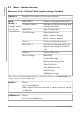
Glossary - Display symbols Batches menu, contains a list of already created batches and the New function for creating a new batch. Batch Modify menu, contains a list of alterable batch settings Statistics menu, contains statistics displays for the open batch.
Glossary Scrolls to the previous menu page (keypad function), altered settings are applied Scrolls to the next menu page (keypad function) Opens the Delete function (keypad function) Cancels the setting process, switches back to previous menu page (keypad function) Battery status indicator (example: fully charged) NF/FE Nonferrous coating material on ferrous base material NC/NF Electrically nonconducting and nonferrous coating material on electrically conducting nonferrous metals WiFi status indicator o
• Largest single reading measured in a block • Largest spot value measured in an Area or Location • Largest mean value of all Area mean values Min • Smallest single reading measured in a block • Smallest spot value measured in an Area or Location • Smallest mean value of all Area mean values RdNo Measurement reading number No Block number USL Upper specification limit n Number of measured blocks nAr Number of measured areas nRd Number of all single readings measured nSp Number of spots measu
Glossary X rd Population mean of all single readings %
In this menu you will find all device information, information about the device status, the software and legal information.
Legal Informations 11 Legal Informations In this chapter you will find all statements on country-specific regulations and directives 11.1 USA, FCC (Federal Communications Commission) FCC ID: 2ATFE-MMSINSPEC00 FCC Regulations This device complies with Part 15 of the FCC Rules. Operation is subject to the following two conditions: (1) this device may not cause harmful interference, and (2) this device must accept any interference received, including interference that may cause undesired operation.
Information about Specific Absorption Rate (SAR) This device is designed and manufactured not to exceed the emission limits for exposure to radio frequency (RF) energy set by the Federal Communications Commission of the United States. During SAR testing, this device was set to transmit at its highest certified power level in all tested frequency bands, and placed in positions that simulate RF exposure in usage near the body.
www.helmut-fischer.