
Quick Installation Guide


Quick Installation Guide
Document
WERA4-Quick-US-200918
Page 5 of 73
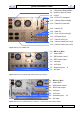
1.0 – Frequency Control Rack
1.8 – Main AC input & Switch
1.9 – DIO72
1.10 – RTU CPCI computer
1.11 – Voltage Status Display
1.12 – Ethernet Connection
1.13 – Control I/O
1.14 – Data I/O
1.15 – Test, I/O (for test only)
1.16 – RF-Driver (RFD)
1.17 – Control Unit (CTU)
1.18 – Control-Status (RSC-Logic)
1.19 – Control Power (RSC-230V)
Figure 2: Back view, WERA FCR
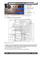
2.0 – REceiver Rack
2.7 – Status RER
2.1 – RER power control
2.2 – RER control input
2.3 – Cal input
2.4 – LoD input
2.5 – Antenna input 1 .. 8
2.6 – AC input
Figure 3.1: Back view, WERA RER internal Filters (8 channels)
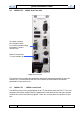
2.0 – REceiver Rack
2.7 – Status RER
2.1 – RER power control
2.2 – RER control input
2.3 – Cal input
2.4 – LoD input
2.5 – Antenna input 1 .. 12
2.6 – AC input
Figure 3.2: Back view, WERA RER (12 channels) – Version with internal Filters (RIN6)