Model OFE/OFG/OEA/OGA-341, 342 SECTION 2. MAINTENANCE 2-1. INTRODUCTION This section provides procedures for the check out and replacement of the various parts used within the fryer. Before replacing any parts refer to the Troubleshooting Section. It will aid you in determining the cause of the malfunction. 2-2. MAINTENANCE HINTS 1. You may need to use a multimeter to check the electric components. 2.
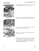
Model OFE/OFG/OEA/OGA-341, 342 1-3. HIGH TEMPERATURE LIMIT CONTROL (Gas Units) (Continued) 2. Using a Phillip’s head screwdriver, remove the screws securing the inner heat shield and remove from unit. Figure 2-3. Figure 2-3 3. Remove the screw securing the high limit bracket to the frame and remove the high limit and bracket from unit. Figure 2-4. Figure 2-4 4. Remove the two screws securing the high limit to the bracket and remove the high limit from bracket. 5.
Model OFE/OFG/OEA/OGA-341, 342 2-3. HIGH TEMPERATURE LIMIT CONTROL (Gas Units) (Continued) Replacement To avoid electrical shock or property damage, move the power switch to OFF and disconnect main circuit breaker, or unplug cord at wall receptacle. 1. If the tube is broken or cracked, the control opens, shutting off electrical power to the heat circuit. The control cannot be reset, and it continuously clicks when pushed. 2. Drain the shortening from the frypot and discard.
Model OFE/OFG/OEA/OGA-341, 342 2-4. COMPLETE CONTROL PANEL REPLACEMENT Should the control board become inoperative, follow these instructions for replacing the board. 1. Remove electrical power supplied to the unit. To avoid electrical shock or property damage, move the power switch to OFF and disconnect main circuit breaker, or unplug cord at wall receptacle. Figure 2-9 2. Remove the two screws securing the control panel and lift out. Figure 2-9. 3.
Model OFE/OFG/OEA/OGA-341, 342 2-5. POWER SWITCH (Continued) 4. With control panel removed, and the wires off the switch, push in on tabs on the switch to remove from panel. Figure 2-12. 5. Replace with new switch, and reconnect wires to switch. 6. Replace the control panel. Figure 2-12 2-6. TEMPERATURE PROBE REPLACEMENT (Gas) The temperature probe relays the actual shortening temperature to the control board. If it becomes disabled, “E06” shows in the display.
Model OFE/OFG/OEA/OGA-341, 342 2-6. TEMPERATURE PROBE 5. Remove the probe from the frypot, and disconnect wire REPLACEMENT (GAS) connector from the control panel. Figure 2-15. (Continued) 6. Place the nut and new ferrule on the new probe and insert the probe into the compression fitting until it extends one (1) inch (2.54cm) into the frypot. Figure 2-16. 7. Tighten hand tight and then a half turn with wrench. Figure 2-15 Excess force will damage probe. 8.
Model OFE/OFG/OEA/OGA-341, 342 2-7. TEMPERATURE PROBE 4. Using a ½ inch wrench, remove the nut on the compression REPLACEMENT fitting. Figure 2-18. (ELECTRIC) (Continued) 5. Remove the probe from the frypot, and disconnect probe. 6. Place the nut and new ferrule on the new probe and insert the probe into the compression fitting until it extends one (1) inch (2.54cm) into the frypot. Figure 2-18 2-8. FLAME SENSOR/ PILOT / IGNITOR ASSEMBLY (GAS) 7.
Model OFE/OFG/OEA/OGA-341, 342 2-8. FLAME SENSOR/ PILOT / IGNITOR ASSEMBLY (Gas) (Continued) 2. Remove the control panel and heat shield from control area. Figure 2-19. Figure 2-19 3. Disconnect the flame sense wire from ignition module. Figure 2-20. Figure 2-20 4. Using a 7/16” wrench, loosen the nut on the pilot tube and pull tube from assembly. Figure 2-21. Figure 2-21 5. Remove the two screws securing the assembly and pull assembly from unit. Figure 2-22. 6.
Model OFE/OFG/OEA/OGA-341, 342 2-9. IGNITION MODULE During normal operation, the ignition modules send 24 volts to the ignitors and gas valve. If a module does not sense a pilot flame, the module starts the ignition process again. But, if a pilot light goes out for longer that 10 seconds, or it goes out 3 times within 10 seconds, the module keeps the 24 volts from reaching the gas valve. The burners shut down. 1. Remove electrical power supplied to the unit.
Model OFE/OFG/OEA/OGA-341, 342 2-10. TRANSFORMER REPLACEMENT The transformer reduces voltage down (to 24V) to accommodate those components with low voltage. 1. Remove electrical power supplied to the unit. To avoid electrical shock or property damage, move the power switch to OFF and disconnect main circuit breaker, or unplug cord at wall receptacle. 2. Remove the control panel Figure 2-26 3. Remove the two wire connectors to disconnect transformer From panel. Figure 2-26. 4.
Model OFE/OFG/OEA/OGA-341, 342 2-12. VACUUM SWITCHThis switch senses the airflow from the induction blower. If REPLACEMENT the airflow is reduced below a set amount, the switch opens and the I/O board cuts power to the gas control valve, which shuts the pilot flame off. 1. Remove electrical power supplied to the unit. Figure 2-29 To avoid electrical shock or property damage, move the power switch to OFF and disconnect main circuit breaker, or unplug cord at wall receptacle. 2. Remove the control panel.
Model OFE/OFG/OEA/OGA-341, 342 2-13. DRAIN MICROSWITCH Upon turning the drain handle, the drain microswitch should REPLACEMENT “open”, cutting off the pilot flame. This will prevent the fryer from heating while shortening is being drained from the frypot. 1. Remove electrical power supplied to the unit. To avoid electrical shock or property damage, move the power switch to OFF and disconnect main circuit breaker, or unplug cord at wall receptacle. 2.
Model OFE/OFG/OEA/OGA-341, 342 2-14. FILTER SWITCH REPLACEMENT (Continued) 3. Label and remove the wires from the switch. With test instrument check across the terminals of the switch. With the switch in the on position, the circuit should be closed. With the switch in the off position, the circuit should be open. If the switch is defective, replace by continuing with this procedure. Figure 2-35. Figure 2-35 4.
Model OFE/OFG/OEA/OGA-341, 342 2-15. GAS CONTROL VALVE REPLACEMENT (Continued) 1. Remove right side panel. Figure 2-37. Figure 2-37 2. Label and remove wires from gas valve. Figure 2-38 Figure 2-38 3. Using a 7/16 wrench, remove the pilot line from the gas valve. Figure 2-39. Figure 2-39 4. Using a 1-inch wrench, loosen the nut securing the main gas inlet line to the gas valve. Figure 2-40.
Model OFE/OFG/OEA/OGA-341, 342 2-15. GAS CONTROL VALVE REPLACEMENT (Continued) 5. Using a pipe wrench, loosen the outlet fitting to the burner. Figure 2-41. Figure 2-41 6. Using a Phillips screwdriver, remove the 2 screws securing the gas valve to the bracket and remove gas valve from unit. Figure 2-42. 7. Remove the fittings from the gas valve and install in new gas valve. Figure 2-42 8. Install the new gas valve in reverse order. 2-16.
Model OFE/OFG/OEA/OGA-341, 342 2-16. BLOWER MOTOR REPLACEMENT (Continued) 3. Remove the wire cover from the blower motor housing. Figure 2-44. Figure 2-44 4. Remove wire nuts connecting blower motor wires to wires in conduit. Figure 2-45. Figure 2-45 5. Loosen conduit from blower motor. Figure 2-46. Figure 2-46 7. Remove screws connecting flue to blower. Figure 2-47.
Model OFE/OFG/OEA/OGA-341, 342 2-16. BLOWER MOTOR REPLACEMENT (Continued) 8. Using 3/8 inch nut driver, remove nuts securing blower to the unit. Figure 2-48. Pull blower from unit. Figure 2-48 9. Install new blower in reverse order. 2-17. HEATING ELEMENTS (ELECTRIC) Heating elements are available for 208 and 230 voltage. Check data plate to determine correct voltage.
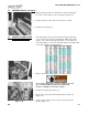
Model OFE/OFG/OEA/OGA-341, 342 2-17. HEATING ELEMENTS (ELECTRIC) (Continued) Replacement 4. Perform an ohm check on one element at a time, with wires disconnected. The 2 elements actually have 3 small heating elements inside the outer plate. It’s important to check between the correct wires to obtain an accurate ohm reading. The wires are labeled for your convenience. If the resistance is not within tolerance, replace the element. Wire Nos.
Model OFE/OFG/OEA/OGA-341, 342 2-18. HEATING CONTACTORS (ELECTRIC) Checkout (Power Removed) Heat Contactor (Mercury) Each well of an electric fryer requires two switching contactors. The first in line is the primary contactor and the second in line is the heat contactor. When open, the primary contactor does not allow power to flow to the heat contactor. When closed, the primary supplies voltage to the heat contactor. When the heat contactor is open, no voltage is supplied to the heating elements.
Model OFE/OFG/OEA/OGA-341, 342 2-18. HEATING CONTACTORS (ELECTRIC) (Continued) To avoid electrical shock, make connections before applying power, take reading, and remove power before removing meter leads. The following checks are performed with the wall circuit breaker closed and the main power switch in the ON position. 1. Re-apply power to unit and turn power switch to ON. 2.
Model OFE/OFG/OEA/OGA-341, 342 2-18. HEATING CONTACTORS (ELECTRIC) Continued) 2. Remove the screws securing the contactor to the shroud, and remove contactor. Figure 2-55. 3. Install new contactor, and see steps 4 and 5. Figure 2-55 Replacement (Primary Contactor) 1. Remove only the wires directly connected to the contactor being replaced. Label the wires for replacement. Figure 2-56. 2. Remove screws securing contactor to unit and remove contactor. Figure 2-57. Figure 2-56 3. Install new contactor.
Model OFE/OFG/OEA/OGA-341, 342 2-19. SPEAKER ASSEMBLY The speaker assembly emits audible signals to let the operator know when cooking and hold times are finished. 1. Remove electrical power supplied to unit. Figure 2-58 To avoid electrical shock or property damage, move the power switch to OFF and disconnect main circuit breaker, or unplug cord at wall receptacle. 2. Remove control panel. 3. Pull the power switch connector from back of panel. Figure 2-58. Figure 2-59 4.
Model OFE/OFG/OEA/OGA-341, 342 2-20. HIGH TEMPERATURE LIMIT CONTROL (ELECTRIC) This high temperature control is a safety, manual reset control, which senses the temperature of the shortening. If the shortening temperature exceeds 425°F (218°C), this switch opens and shuts off heat to the frypot, and E10 shows in control display. When the temperature of the shortening drops to a safe operation reset the high limit by pressing the reset button.
Model OFE/OFG/OEA/OGA-341, 342 2-20. HIGH TEMPERATURE LIMIT CONTROL (ELECTRIC) (Continued) 4. Pull back cardboard cover and remove the two electrical wires from the high temperature limit control. Figure 2-66. Figure 2-66 5. Manually reset the control, then check for continuity between the two terminals after resetting the control. If the circuit is open, replace the control, then continue with this procedure. (If the circuit is closed, the high limit is not defective. Reconnect the two electrical wires.
Model OFE/OFG/OEA/OGA-341, 342 2-20. HIGH TEMPERATURE LIMIT CONTROL (ELECTRIC) (Continued) 4. Straighten the capillary tube, and pull capillary tube through the hole in the element hinge, from the rear of the fryer. 5. Remove the defective control from the fryer. Figure 2-69 6. Straighten the capillary tube on the new high limit, and thread the capillary tube through the hole in the element hinge. Figure 2-69. 7. Reattach the capillary to the brackets on the upper and lower parts of the elements.
Model OFE/OFG/OEA/OGA-341, 342 2-21. FILTER PUMP AND MOTOR REMOVAL 1. Remove electrical power supplied to unit. To avoid electrical shock or property damage, move the power switch to OFF and disconnect main circuit breaker, or unplug cord at wall receptacle. 2. Open the door (left door on 2 well units), and remove the 2 screws securing the switch box cover and pull filter motor wires from filter switch. Figure 2-70. Figure 2-70 3. Remove the 2 screws securing the switch box to the frame.
Model OFE/OFG/OEA/OGA-341, 342 2-21. FILTER PUMP AND MOTOR REMOVAL (Continued) 7. Remove left side panel. 8. Using 9/16” socket or wrenches, remove the bolts and nuts securing the motor to the bracket and pull pump, motor, and piping from unit. Figure 2-74. Figure 2-74 2-22. AUTOLIFT TRANSFORMER REPLACEMENT (if applicable) 1. Remove electrical power supplied to unit.
Model OFE/OFG/OEA/OGA-341, 342 2-23. AUTOLIFT PC BOARD REPLACEMENT (if applicable) Autolift PC Board 1. Remove electrical power supplied to unit. To avoid electrical shock or property damage, move the power switch to OFF and disconnect main circuit breaker, or unplug cord at wall receptacle. 2. Remove control panel 3. Disconnect connectors from PC board. Figure 2-77 4. Using 5/16” nut-driver or wrench, remove the 4 nuts securing the autolift PC board to the panel and remove PC board from panel. 5.
Model OFE/OFG/OEA/OGA-341, 342 2-24. AUTOLIFT ACTUATOR (MOTOR) REPLACEMENT (if applicable) 5. Disconnect actuator connector. Figure 2-80. Figure 2-80 6. Remove female connector from plate. Figure 2-81. Figure 2-81 Figure 2-82 7. Using 7/16” socket, remove the 4 nuts securing the support plate. 2 nuts are behind the insulation. Figures 2-82 & 2-83.
Model OFE/OFG/OEA/OGA-341, 342 2-24. AUTOLIFT ACTUATOR (MOTOR) REPLACEMENT (if applicable) 8. Remove the 2 top screws securing the support plate and remove the plate from the unit. Figure 2-84. Figure 2-84 9. Using a 15T torx driver, remove the 2 torx screws from the back shroud, and pull the actuator from the unit. Figure 2-85. Figure 2-85 2-30 10. Install new actuator in reverse order.