6000 Series Electronic Steam Humidifiers Installation Operation Service OWNER’S MANUAL The 6000 Series Humidifiers represent that latest in humidification technology. Please read these instructions carefully for trouble free operation and to get the most out of your purchase. For further information concerning this product, contact your local Herrmidifier representative.
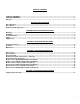
TABLE OF CONTENTS TABLE OF CONTENTS...................................................................................................................................................... 3 SECTION I WARRANTY..................................................................................................................................................... 3 Warranty ................................................................................................................................................
SECTION I WARRANTY Warranty 1. Herrmidifier warrants to the buyer or any user during the duration of the Warranty that the humidifier described in this manual will be free from defects of material and workmanship for a period of two (2) years from the date of shipment. 2. For this Warranty to be effective, this humidifier must be installed, operated and maintained in accordance with the Installation Instructions, Operations and Maintenance Manual(s) supplied with the humidifier. 3.
SECTION II UNIT OPERATION Basic Operation Controlled humidification requires a very precise control system. The 6000 utilizes a solid state control to monitor performance and maintain humidity. The humidifier evaluates the operation and alerts the operator to problem conditions and prevents undesirable operation. On initial start-up or a call for humidity, the humidifier will attempt to fill to its full load amp rating. The unit will not necessarily have a full cylinder of water.
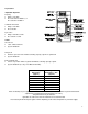
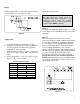
Key Features Adjustable Setpoints Capacity • Range = 50-100% • Preset at 100% for 6000-1,3,4 Preset at 50% for 6000-2 Low Drain Threshold • Range = 50-100% • Preset at 90% Cycle Time • Range = 60-300 seconds • Preset at 60 seconds Faults Overcurrent • 138% of Rated Current • System Shutdown Fill System • Fill valve open for 6 hours without achieving capacity setpoint or cylinder full • System Shutdown End of Cylinder Life • 6 hours of operation while on cylinder full without achieving capacity setpoint • S
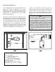
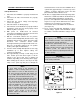
Engineering and Application The Herrmidifier 6000 Series Steam Humidifiers can be applied in a variety of applications. The simplest application is to utilize the model with the built-in blower package (6000-1,2). The steam generated by the unit is distributed into the conditioned space by the built-in blower package (Figure 1). Alternatively, steam generated by the "6000" unit can be discharged directly into the system ductwork (6000-3,4).
SECTION III INSTALLATION INSTRUCTIONS Mounting Plumbing The cabinet is designed to safely contain the working components of the Herrmidifier 6000 series humidifier and dissipate heat to protect the electronics. Locate humidifier, steam pipe and accessories in a manner to allow routine inspection and any necessary maintenance. DO NOT install the unit above (such as false ceilings) or around valuable property, where a malfunction could cause damage.
Steam Distribution Blower Version (6000-1,2) The 6000 Series Steam Humidifier with the built in blower pack should be mounted a minimum of 18” from the ceiling. There should also be 5' of horizontal clearance in front of the unit to prevent stem from condensing on obstructions (See Figure 1). There is an adjustable louver to adjust the direction of the steam plume.
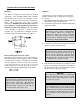
Wiring All field wiring should be routed up through the knockout in the bottom panel or in the back of the unit. Control Circuit Connections WARNING! Do Not install any controls inside the Herrmidifier 6000 cabinet. Installations of any extraneous devices inside the electrical compartment rnay cause erratic behavior of the circuitry and will VOID the warranty. Figure 7 Supply Power. 1. Insure that minimum circuit ampacity is 15 amps. 2.
SECTION IV OPERATING INSTRUCTIONS Start-up Instructions 1. Check that the humidifier is properly mounted and level. 2. Check that the water fill and drain are properly connected. 3. Check that the correct voltage and amperage services are supplied. 4. Check all controls are wired properly. 5. Check that the steam distributor is properly installed and that the steam hose has been properly routed without any kinks or flat spots. 6.
Checklist Figure 10 NOTE The Herrmidifier 6000 Humidifier checklist is provided to help the installer insure a successful installation. If further assistance is needed from the Herrmidifier representative or the factory, the checklist is expected to be completed. If a jobsite visit is required from the Herrmidifier representative or the factory, and the checklist has not been accurately completed, additional charges will be required by the individual(s) representing Herrmidifier.
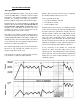
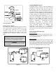
Maintenance To maintain output, the water level in the cylinder will slowly move upwards, exposing new electrode to the water as the electrodes become coated with minerals. Eventually, all of the usable electrode surfaces will be coated and the cylinder will be full of water. At this point, the output will begin to fall and the red “service" light will come on. The unit will shutdown.
SECTION V TROUBLESHOOTING GUIDE All Herrmidifier 6000 Series Humidifiers are manufactured under strict quality control and are subjected to a complete operational test. All circuit board adjustments are made at the factory and should not be adjusted beyond the guidelines set in this troubleshooting guide without first consulting a factory representative. The following information is for your help and reference.
Problem / Symptom Overcurrent The alarm condition occurs when an overcurrent situation (>138% of rated current) has occurred and the humidifier has shut down to prevent any damage. This alarm indicates that there has been a significant reduction in resistance between the main legs of the supply power and the humidifier has been shut down to prevent damage and should be serviced before it is restarted. Overcurrent LED CR 17 (Figure 12) is illuminated.
Non-Fault Activated Problems: Problem / Symptom 24 VAC circuit breaker trips as soon as power switch is turned “on”. 24 VAC circuit breaker trips after the unit is turned on for about 15 seconds. 24 VAC Circuit breaker trips whenever the drain valve activates Humidifier turned on but will not operate. Power lamp is “off”. Unit turned “on”. Contractor pulled in, but no water is entering the cylinder. Excessive arcing in cylinder Unit fills to the cylinder full condition and remains cold.
Non-Fault Activated Problems – Cont’d Problem / Symptom Reason - Correction Water “foaming” inside the cylinder. Check drain valve and insure that water drains freely. If necessary, clean or replace valve if defective. Check water supply. If it is commercially softened, either increase the drain threshold (R18) to 92% or reconnect the unit to raw water. Drain and restart the unit. If the unit is connected to a hot water line, reconnect to the cold water line.
Blower Version Wiring Diagram(6000-1 and 6000-2) 17
Blower Version Exploded View (6000-1 and 6000-2) 18
Blower Version Parts List (6000-1 and 6000-2) 1845 Door Interlock 1826 Humidistat Element EST-003 Cylinder Full Interface (Set to “A”) EST-105A Toroid Transformer EST-1001B Main Circuit Board EST-1062 Drain Cup EST-1124 Terminal Strip EST-1141 Red Lamp EST-1142 Green Lamp (2) EST-1143 On Off Drain Switch EST-1146 KEP Nut, 6-32 EST-1147 KEP Nut, 8-32 EST-1405 Timer/Relay EST-1407 Knol EST-1409 Universal Bushing EST-1501 Steam Manifold EST-1512 Transformer 115/230 to 24 VAC EST-1513 Distribution Louver EST-15
Ducted Version Exploded View (6000-3 and 6000-4) 20
Ducted Version Parts List (6000-3 and 6000-4) 1845 Door Interlock EST-003 Cylinder Full Interface (Set to “A”) EST-105A Toroid Transformer EST-596 Steam Hose EST-1001B Main Circuit Board EST-1062 Drain Cup EST-1124 Terminal Strip EST-1141 Red Lamp EST-1142 Green Lamp (2) EST-1143 On Off Drain Switch EST-1146 KEP Nut, 6-32 EST-1147 KEP Nut, 8-32 EST-1409 Universal Bushing EST-1512 Transformer 115/230 to 24 VAC EST-1513 Distribution Louver EST-1514 Relay, 2 pole, 20 A EST-1519 Circuit Breaker, 2A EST-1525 Dra
Ducted Version Wiring Diagram (6000-3 and 6000-4) 22
SECTION VI SUGGESTED SPECIFICATIONS Suggested Specifications Part I-Scope • Furnish a system of humidification for the areas known as______________________________________. • Operation of the system shall be controlled automatically to maintain _____%R.H. at_____ (F with a tolerance of +/______%R.H. • Warrant the system for a period of two years from date of shipment (except for the replaceable steam cylinder). • Provide (1) owner's manual to cover installation, start-up, operation and maintenance.
Herrmidifier Office: 101 McNeill Road • Sanford, NC 27330 Phone: 800-884-0002 • Fax: 919-777-6300 • www.herrmidifier.com• email: herrsales@therrmidifier.com Part No. OM 273 • ©2003, Trion, Inc.