
Owner's Manual


H8 DSP
Digital Interface Processor
User’s manual
1
2
3
4
5
6 7
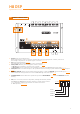
18: Yellow +BATT
20: Black -BATT
7: Brown OPTICAL SEL
17: Orange AUX SEL
6: Pink MEM A SEL
16: Pink/Black MEM B SEL
10: Cyan KEY MEM
5: Red REM IN
15: Red REM IN
9: Blue REM OUT
4
7
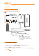
1. POWER SUPPLY.
+BATT 12V: 12V Power supply positive connection terminal.
-BATT: Power supply negative connection terminal (GND).
WARNING: make sure the connection polarity is as indicated on the terminals. A misconnection may result in
damage to the H8 DSP.
After connecting to power supply, wait at least 10 seconds before turning the H8 DSP on.
2. REMOTE IN-OUT.
REM IN: input for the processor remote turn on through the source Remote Out signal.
REM OUT: output to turn on other devices / amplifiers connected after the processor.
From the REMOTE-IN signal, the processor only takes 1 second to supply the signal to the REM OUT output.
The 130 mA output current capability can also drive an automotive relay (making sure it doesn’t exceed 130 mA).
WARNING: the H8 DSP must be switched on before any amplifiers are turned on.
The system sources Remote Out must be connected to the product REM IN, and the product REM OUT
is then to be connected to the Remote In of other devices / amplifiers.
4.4 INPUTS – REMOTE CONTROL OUTPUTS AND POWER SUPPLY