
Owner's Manual


H8 DSP
Digital Interface Processor
User’s manual
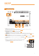
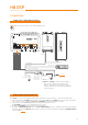
Fig. 1
AUX SEL
OPTICAL SEL
TO + 12 V TO + 12 V
Fig. 3
TO GND TO GND
MEM A SEL
MEM B SEL
Fig. 2
AUX SEL
OPTICAL SEL
Fig. 4
MEM A SEL
MEM B SEL
4
TO + 12 V TO + 12 V
TO GND TO GND
8
3. KEY MEM:
To turn the processor on and off when the vehicle ignition is turned on / off.
Remark:
This signal is memory-dependent: if the processor was turned off by a car sub-key connected to the KEY MEM,
it will turn on again by turning the ignition key on. If the processor was turned off by a different method (e.g. DRC)
while the KEY MEM was still active, it will not turn on again through the KEY MEM and you will have to turn it on by
using either the DRC or REM IN.
4. OPTICAL SEL / AUX SEL:
Selection of the auxiliary OPTICAL or AUX inputs. The terminals can be set up with positive or negative selection. This
function is active at + 12V by setting up the UCS switch as shown in fig. 1, while to obtain a –BATT (GROUND) set up
the switch as shown in fig. 2.
5. MEM A SEL / MEM B SEL:
Selection of the DSP “MEM A” o “MEM B” memories. The terminals can be set up with positive or negative
selection. This function is active at + 12V by setting up the UCS switch as shown in fig. 3, while to obtain a –BATT
(GROUND) set up the switch as shown in fig. 4.
6. DRC:
DRC (Digital Remote Control) connection to configure the processor.
7 USB:
USB (type B) connection plug, to connect the processor to a PC and manage its functions through the H8 DSP
software. The connection standard is USB 1.1 / 2.0 / 3.0 compatible.