
Owner's Manual


H8 DSP
Digital Interface Processor
User’s manual
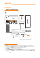
MEM A SEL
AUX SEL
MEM B SEL
OPTICAL SEL
4
TO + 12 V
TO GND
6
5 4 7
9
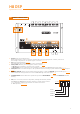
1. IN level: Input signals adjustments.
By turning the knobs counter-clockwise, sensitivity decreases; by turning them clockwise, it increases.
This setting is important for an optimal signal / noise ratio (see 8.1 - 8.2).
2. CLIP: Input clipping detector (see 8.1.9).
If the LED lights up, it indicates clipping on the selected input.
3. DE-EQ CHECK: When lit, the meaning varies based on state (see 6.2).
• LED ON: A de-equalization curve has been recorded.
• LED Flashing: You are performing a de-equalization/analysis of the MASTER main input signal (see 8.1.9).
4. DE-EQ SET: Button to activate analysis or de-equalization functions during system calibration without using a PC
(see 6.2).
5. SPEAKER TURN ON: Switch OFF to prevent turning the device on from the MASTER high-level main input (see 4.2.1 ).
Switch ON allows turning the device on from the MASTER high-level main input (see 5.4).
6. UPGRADE MODE: Switch ON allows to update the product in RESCUE MODE (see 9.4) and the POWER LED will start
flashing.
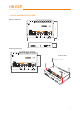
7. UCS (User Control Set): 4 selectors dip switch, enabling the AUX SEL, OPTICAL
SEL, MEM A SEL, MEM B SEL terminals activation. The dip switch selection
(see fig.1) determines whether the terminals are active at +12 Volt or
to -BATT (Ground). (see 4.4.4 / 4.4.5).
4.5 CONTROLS AND SETTINGS
2
1
3