
Instructions / Assembly


EVAPORATIVE COOLER MOTOR INSTRUCTION
WARNING: FAILURE TO FOLLOW INSTRUCTIONS AND USE SAFE ELEC-TRICAL PROCEDURES COULD RESULT IN
SERIOUS INJURY SUCH AS SHOCK OR ELECTROCUTION.
SAFETY PRECAUTIONS:
1. Disconnect electrical power at source before
working on or near a motor or its connected load.
2. This motor must be grounded by attaching the
power supply green ground wire to motor terminal
green screw.Install all wiring, fusing and grounding
in accordance with National Electrical Code, local
requirements, and according to cooler
manufacture’s insturctions.
3. Caution: Motor may stop and restart without
warning. If motor is “overloaded”, it will become
unusually hot and the automatic internal overload
switch will cause the motor to stop. The motor will
then automatically restart after cooling down. An
“overloaded” motor will cycle on and off. If this
occurs, see Motor Pulley Adjustment Section.
4. Keep all parts of body and loose clothing clear from
belts, pulleys and other exposed parts at all times.
Installation Instructions
1. Motor Mounting:
Place motor in motor mounting bracket with vent
holes down. Be sure groove in rubber mounting
rings seats securely on mounting bracket. Tighten
clamps.
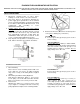
2. Motor Pulley and Blower Pulley Alignment:
Pully must be aligned per Figure 1. If necessary,
loosen pulley set screws with 5/32 Allen wrench.
Each set screw must seat securely on flat of shaft.
3. Belt Tension:
Adjust belt to deflect ½ to ¾ inch at center of span
as per Figure 2. Readjust belt tension after any
pulley adjustment. Replace worn of damaged belts.
4. Electrical Connection (Disconnect electrical power
source prior to making any connections)
115 VAC Motors:
A. Connect green wire (ground) to green screw of
motor housing.
Two Speed Motors:
Connect white wire (common) to white terminal,
black wire (source-high speed) to black terminal
(HI) and red wire (source-low speed) to red
terminal (LO) per Figure 4. Caution: Do not
apply voltage across HI to LO.
230 VAC Motors:
Connect green wire (ground) to green screw of
motor housing.
Two Speed Motors:
Connect orange wire (first leg of source) to
white terminal, black wire (second leg of
source-high speed) to black terminal (HI) and
red wire (second leg of source-low speed) to
red terminal (LO) per Figure 6. Caution: Do not
apply voltage across HI to LO.