
Use and Care Manual


©2018 Hestan Commercial Corporation
21
EN
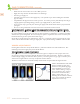
AIR SHUTTER ADJUSTMENT
Remove the control panel to gain access to the
orifice area and air shutters on the burners. A
metal cap at the inlet of the burner called the
“AIR SHUTTER” regulates the amount of air
that enters into the burner for combustion
(see Fig. 4). The air shutter has a lock screw
which must be loosened prior to adjustment.
Remove the burner carefully from the grill.
With a marker pen, mark the current location
of the shutter opening, then loosen the screw
of the air shutter. Reinstall the burner. Make
certain that the burners are sitting properly on
the orifices taking care not to move or damage
the igniter electrodes. Reinstall the radiant trays.
Light the burner and adjust as follows:
• Turn the valve on “HIGH”, light the burner and allow it to warm up for 10 minutes. Be
careful because the burner will be hot from this point forward.
• If the flame is yellow, indicating insufficient air, turn the air shutter counter-clockwise to
allow more air to the burner.
• If the flame is noisy and tends to lift away from the burner ports, indicating too much air,
turn the air shutter clockwise to reduce the amount of air to the burner.
• Once you have established a good flame, make a new mark with the marker pen.
• Remove the burner again and retighten the lock screw of the air shutter taking note of your
newly marked position.
• Repeat this process for each burner.
• Perform one last check that all burners are properly seated on their orifices and rear hanger
bracket.
• Reinstall all radiant trays and cooking grates.
• Reinstall the control panel and control knobs.
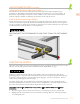
BURNER REMOVAL BEFORE
AIR SHUTTER ADJUSTMENT
Open your grill and remove the grates,
radiant trays, and burners from the
firebox area. Trellis burners are removed
by lifting up the rear of the burner, and
carefully twisting to clear the igniter
shroud. Sear burners have a small metal
cover over the igniter which must be
removed first. There is also a screw at
the rear firebox wall which must be
removed. The sear burner can then
be carefully removed using the same
twisting action to avoid breaking the
ceramic igniter.
GAS CONNECTIONS
(continued)
Figure 4