INDOOR COOKING Vent Hood – Pro Canopy KVP Installation, Use and Care Manual
IF THE INFORMATION IN THIS MANUAL IS NOT FOLLOWED EXACTLY, A FIRE OR EXPLOSION MAY RESULT CAUSING PROPERTY DAMAGE, PERSONAL INJURY, OR DEATH. Do not store or use gasoline or other flammable vapors and liquids in the vicinity of this or any other appliance. Installation and service must be performed by a qualified installer or service agency. DO NOT REPAIR, REPLACE OR REMOVE ANY PART OF THE APPLIANCE UNLESS SPECIFICALLY RECOMMENDED IN THE MANUAL.
Message from Hestan: Hestan’s award-winning culinary innovations and purpose-built features reinvented the restaurant kitchen and redefined culinary experience in some of America’s most acclaimed restaurants. Hestan now takes this performance from the back of the house and puts it front and center in yours. Thoughtfully designed and meticulously built, Hestan will serve you beautifully for years to come. Hestan is the only residential brand born from the dreams and demands of professional chefs.
TABLE OF CONTENTS 1 4 4 5 5 6 9 10 11 18 19 20 20 SAFETY PRECAUTIONS - BEFORE YOU BEGIN MODEL NUMBERS RATING LABEL REGULATORY / CODE REQUIREMENTS USING THE VENTILATION SYSTEM CLEANING AND MAINTENANCE TROUBLESHOOTING DUCTING DO’S AND DON’TS INSTALLATION VENT ACCESSORIES DUCT COVERS PARTS / SERVICE LIMITED WARRANTY EN SAFETY PRECAUTIONS - BEFORE YOU BEGIN When properly cared for, your Hestan ventilation system will provide safe, reliable service for many years.
SAFETY PRECAUTIONS - BEFORE YOU BEGIN (CONT.) GENERAL SAFETY PRECAUTIONS When properly cared for, your new Hestan ventilation hood has been designed to be a safe, reliable ventilation system. Read all instructions carefully before using this ventilation system. When using kitchen appliances, basic safety precautions must be followed. EN TO REDUCE THE RISK OF FIRE, ELECTRIC SHOCK, OR INJURY TO PERSONS, OBSERVE THE FOLLOWING: a) Use this ventilation system only as intended by the manufacturer.
SAFETY PRECAUTIONS - BEFORE YOU BEGIN (CONT.) EN BURN HAZARD This ventilation system is intended for use with ranges or cooktops, which can get very hot during operation. Observe the warnings and cautions for the cooking appliance. This ventilation system should be serviced only by a Hestan authorized service technician. Contact the nearest authorized service center for examination, repair or adjustment. Do not repair or replace any part of the system unless specifically recommended.
MODEL NUMBERS MODEL NO. EN DESCRIPTION BLOWER PACKAGE KVP30 30” Pro Canopy 600 cfm Kitchen Ventilation System WM2L Dual KVP36 36” Pro Canopy 600 cfm Kitchen Ventilation System WM2L Dual KVP42 42” Pro Canopy 900 cfm Kitchen Ventilation System WM2L Dual + WM1L Single KVP48 48” Pro Canopy 1200 cfm Kitchen Ventilation System Two WM2L Duals KVP54 54” Pro Canopy 1200 cfm Kitchen Ventilation System Two WM2L Duals POWER AND FLOW RATINGS Minimum Round Duct Size 8” (50 in.
REGULATORY / CODE REQUIREMENTS Installation of this ventilation system must be made in accordance with local codes. In the absence of local codes, this unit should be installed in accordance with the National Electrical Code and local codes. EN This appliance must be electrically grounded in accordance with local codes or in the absence of local codes with the National Electrical Code ANSI/NFPA 70, or Canadian Electrical code CSA C22.1.
CLEANING AND MAINTENANCE CLEANING THE VENTILATION SYSTEM Cleaning requirements depend completely on usage and environment. The more high-heat and/or greasy cooking, the more often the hood and blower will need cleaning. EN The grease tray and blower aren’t visible from the outside, so they must be removed for inspection. After you’ve inspected the tray a few times over the course of six months or a year, you’ll be able to set a cleaning schedule according to your usage pattern.
CLEANING AND MAINTENANCE (CONT.) CLEANING Clean the shield(s) and/or blower housing(s) in a sink of warm soapy water (liquid dish detergent) and let soak for a few minutes. Wash with a sponge or dishcloth, rinse and let drain before reinstalling. Alternatively, the blower housing(s) and blower shield(s) may be placed into a dishwasher.
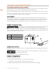
CLEANING AND MAINTENANCE (CONT.) BLOWER WHEEL REMOVAL For instances where the blower wheel must be removed, follow the instructions below. EN • Removing the blower wheel requires a 1/8” hex wrench. This may be obtained from your local hardware store or tool supply. The wheel is retained by a set screw on the side of the hub of the wheel that tightens up against a “flat” spot on the motor shaft. 1. Locate the set screw on the side of the hub of the wheel. 2.
CLEANING AND MAINTENANCE (CONT.) MOTOR REPLACEMENT To reduce the risk of personal injury, turn off power to the hood at the breaker or the circuit disconnect before attempting to remove the blower motor. EN MOTOR IDENTIFICATION AND POSITIONING Motors are color-coded; black and white motors have different rotations and must be installed in the correct positions. • • Housings with a single blower use a white blower and wheel. Housings with two blowers use a white blower on the right and black on the left.
DUCTING DO’S AND DON’TS GENERAL REQUIREMENTS Observe local codes regarding special duct requirements and placement of duct work against combustibles. EN • • • • Using recommended transitions (see VENT ACCESSORIES) will ensure proper efficiency. Using recommended roof caps or wall louvers (see VENT ACCESSORIES) will ensure proper efficiency. Use foil HVAC tape (not grey cloth duct tape) to seal all joints. The hood must be ducted to the outdoors without restrictions.
INSTALLATION TO REDUCE THE RISK OF FIRE, ELECTRIC SHOCK, OR INJURY TO PERSONS, OBSERVE THE FOLLOWING: EN a) Installation work and electrical wiring must be done by qualified person(s) in accordance with all applicable codes and standards, including fire-rated construction. b) Sufficient air is needed for proper combustion and exhausting of gases through the flue (chimney) of fuel burning equipment to prevent back drafting.
INSTALLATION (CONT.) 4. IF THE HOOD IS TO BE “BACK VENTED”, PROCEED DIRECTLY TO STEP 5. Consult the connection diagrams (following) for further details on exhaust outlet placement. Method 1: Install the duct(s) from the outside of the home down to the location of the exhaust outlet(s) on the top of the hood or to the transition (if applicable). EN • If a transition is used, install duct down to the location of the transition outlet plus 1”. This will allow the transition to engage 1” inside of duct.
INSTALLATION (CONT.) Connection Diagram (42” width) 5-1/2" [14 cm] (Wall Side) 7-5/16" [18.6 cm] 7-5/16" [18.6 cm] Motor Cooling Vent (3) Electrical (2) 8" Round 1-7/8" [4.8 cm] 5-1/4" [13.3 cm] 1-3/4" [4.4 cm] Centerline of hood 6" [15.2 cm] Round WM2L Dual + WM1L Single Blower (900 CFM) EN (Top View) Connection Diagram (48-54” widths) 5-1/2" [14 cm] 1-3/4" [4.4 cm] 11" [29.9 cm] Motor Cooling Vent (4) 11" [29.9 cm] (Wall Side) Electrical (2) 5-1/4" [13.3 cm] 8" [20.
INSTALLATION (CONT.) 8. WIRING PREPARATION: a) Install an appropriate 1/2” UL listed electrical wire clamp through each motor box electrical opening on top of the hood. EN b) Install electrical wiring from the service panel to the hood location for each motor box. Consult the connection diagrams (on previous page) for further details on electrical placement. See “ELECTRICAL SUPPLY AND GROUNDING” on page 1 for power requirements. Method 1: Extend wiring to 30” above the countertop.
INSTALLATION (CONT.) 12. FOR BACK VENTING APPLICATIONS ONLY. IF NOT BACK VENTING, PROCEED DIRECTLY TO STEP 13. • • EN Note: Wall studs may interfere with back venting installations. Additional framing may be required. It is necessary to cut duct access hole(s) in the wall prior to installing the hood. If using a duct cover, this step may be done with the duct cover removed from the hood. The duct cover must still be mounted to the hood before mounting the hood to the wall.
INSTALLATION (CONT.) Method 2: a) Place the appropriate elbow(s) on the top of the hood. Elbow(s) should be placed with the non-crimped end(s) on the inside of the collar(s) of the exhaust outlet(s). Use HVAC foil tape (not grey cloth duct tape) to seal joints. EN b) Insert the electrical wire from the service panel into the electrical wire clamp on each motor box. Tighten the wire clamp(s).
INSTALLATION (CONT.) 17. WIRING CONNECTION: From inside the hood, using UL listed wire nuts, attach the “neutral” wire(s) to the white lead(s), the “hot” wire(s) to the black lead(s), and the ground wire(s) to the green lead(s) inside the motor box(es). EN DO NOT OPERATE HOOD WITHOUT PROPER GROUND CONNECTION. 18. Install the blower motor(s) by plugging the wiring connectors in and securing the blower motor(s) using the retaining screws that were removed in Step 7. 19.
VENT ACCESSORIES WALL LOUVER WALL LOUVER EN A: 11” B: 13” A, B: 8-5/8” Back View A: 6” B: 8” Back View A: 11” B: 13” 1-½” Flange 1-½” Flange ITEM MODEL A AKVWL6 AKVWL8 B DESCRIPTION ITEM 6” Round 8” Round 12” DESCRIPTION AKVWL10 AKVWL12 A B LOW PROFILE ELBOW MODEL 10” Round 12” Round MULTI-BLOWER TRANSITION A: 10” B: 12” 8-½” A: 17-½” B: 16-½” 6” 16” 8” Round MODEL A: 23-¼” B: 30-½” DESCRIPTION ITEM AKVBE8 8” Round to 6” x 8-1/2” Rect.
DUCT COVERS USE WITH HOOD MODEL # HESTAN MODEL # DESCRIPTION KVDC3012 DUCT COVER, VENTILATION, 30W X 12H KVP30 KVDC3012-XX DUCT COVER, VENTILATION, 30W X 12H (COLOR) KVP30 KVDC3612 DUCT COVER, VENTILATION, 36W X 12H KVP36 KVDC3612-XX DUCT COVER, VENTILATION, 36W X 12H (COLOR) KVP36 KVDC4212 DUCT COVER, VENTILATION, 42W X 12H KVP42 KVDC4212-XX DUCT COVER, VENTILATION, 42W X 12H (COLOR) KVP42 KVDC4812 DUCT COVER, VENTILATION, 48W X 12H KVP48 KVDC4812-XX DUCT COVER, VENTILATION, 48W X
PARTS / SERVICE SERVICE DATA RECORD The rating label contains the model number and serial number of the appliance. See page 4 for the location of the rating label. EN Now is a good time to write this information in the space provided below. Keep your invoice for warranty validation.
LIMITED WARRANTY (CONT.) Purchaser is responsible for making the Product reasonably accessible for service or for paying the cost to make the Product reasonably accessible for service. Service is to be provided during normal business hours of the authorized Hestan Commercial Service Provider. To the extent Purchaser requests service outside of the normal business hours of the authorized Hestan Commercial Service Provider, Purchaser will pay the difference between regular rates and overtime or premium rates.
LIMITED WARRANTY (CONT.) ASSUMES NO RESPONSIBILITY THAT THE PRODUCT WILL BE FIT FOR ANY PARTICULAR PURPOSE, EXCEPT AS OTHERWISE PROVIDED BY APPLICABLE LAW. EN HCC SHALL NOT BE LIABLE FOR LOSS OF REVENUE OR PROFITS, FAILURE TO REALIZE SAVINGS OR OTHER BENEFITS, OR ANY OTHER SPECIAL, INCIDENTAL OR CONSEQUENTIAL DAMAGES CAUSED BY THE USE, MISUSE OR INABILITY TO USE THE PRODUCT, REGARDLESS OF THE LEGAL THEORY ON WHICH THE CLAIM IS BASED, AND EVEN IF HCC HAS BEEN ADVISED OF THE POSSIBILITY OF SUCH DAMAGES.
LE NON-RESPECT À LA LETTRE DE CES INSTRUCTIONS PEUT CAUSER UN INCENDIE OU UNE EXPLOSION, QUI POURRAIT ENTRAÎNER DES DOMMAGES MATÉRIELS, DES BLESSURES OU LA MORT. Ne pas entreposer ou utiliser d’essence ou tout autre liquide ou gaz inflammable à proximité de cet appareil ou de tout autre appareil. L’installation et le service doivent être effectués par un installateur qualifié ou une agence de service.
Un message de Hestan Les innovations culinaires primées de Hestan et les caractéristiques spéciales ont réinventé la cuisine du restaurant et redéfini l’expérience culinaire dans certains des restaurants les plus acclamés de l’Amérique. Hestan prend maintenant cette performance à l’arrière de la maison et la met au centre de la vôtre. Pensé et méticuleusement conçu, Hestan vous servira magnifiquement pour les années à venir.
TABLES DES MATIERES 1 4 4 5 5 6 9 10 11 19 20 21 21 PRÉCAUTIONS DE SÉCURITÉ - AVANT DE COMMENCER NUMÉROS DE MODÈLE PLAQUE SIGNALÉTIQUE RESPECT DE LA RÉGLEMENTATION ET DES CODES EN VIGUEUR MODE D’EMPLOI NETTOYAGE ET ENTRETIEN DÉPANNAGE BONNE PRATIQUE DE CANALISATION INSTALLATION ACCESSOIRES DE VENTILATION CACHE-CONDUIT PIÈCES / SERVICE GARANTIE LIMITÉE FR PRÉCAUTIONS DE SÉCURITÉ - AVANT DE COMMENCER Lorsque votre système de ventilation Hestan est correctement entretenu, il assure un service sûr et fiable
PRÉCAUTIONS DE SÉCURITÉ - AVANT DE COMMENCER (SUITE) PRÉCAUTIONS GÉNÉRALES DE SÉCURITÉ Lorsqu’il est correctement entretenu, votre hotte de ventilation est un système de ventilation sûr et fiabl. Lisez attentivement toutes les instructions avant d’utiliser ce système de ventilation. Lors de l’utilisation d’appareils de cuisine, des précautions de sécurité de base doivent être respectées.
PRÉCAUTIONS DE SÉCURITÉ - AVANT DE COMMENCER (SUITE) RISQUE DE BRÛLURE Ce système de ventilation est conçu pour être utilisé avec des cuisinières ou tables de cuisson, qui peuvent devenir très chauds pendant le fonctionnement. Respectez les avertissements et les mises en garde concernant l’appareil de cuisson. FR Ce système de ventilation doit être réparé uniquement par un technicien agréé Hestan. Contactez le centre de service agréé le plus proche pour l’examen, la réparation ou le réglage.
NUMÉROS DE MODÈLE VENTILATEURS UTILISÉS NO.
RESPECT DE LA RÉGLEMENTATION ET DES CODES EN VIGUEUR L’installation de cet appareil de cuisson doit être effectuée conformément aux codes locaux. En l’absence de tels codes, installer cet appareil conformément au National Electrical Code et les codes locaux. Tous les composants électriques doivent mis à la terre conformément aux codes locaux ou, en l’absence de tels codes, au National Electrical Code ANSI/NFPA 70 ou au Code national de l’électricité du Canada CSA C22.1.
NETTOYAGE ET ENTRETIEN NETTOYAGE DU SYSTÈME DE VENTILATION Les exigences de nettoyage dépendent entièrement de l’utilisation et de l’environnement. Plus la cuisson est chaude et /ou grasse, plus le hotte et le souffleur doivent être nettoyés. Le bac à graisse et le soufflante ne sont pas visibles de l’extérieur, ils doivent donc être retirés pour inspection.
NETTOYAGE ET ENTRETIEN (SUITE) NETTOYAGE Nettoyez le(s) bouclier(s) et /ou le(s) boîtier(s) du soufflante dans un évier d’eau chaude savonneuse (détergent à vaisselle liquide) et laissez tremper pendant quelques minutes. Laver avec une éponge ou un torchon, rincer et laisser égoutter avant de réinstaller. Il est également possible de placer le(s) boîtier(s) de la soufflante et le(s) bouclier(s) de la soufflante dans un lave-vaisselle.
NETTOYAGE ET ENTRETIEN (SUITE) RETRAIT DE LA ROUE Pour les cas où la roue de soufflante doit être retirée, suivez les instructions ci-dessous. • Le retrait de la roue de soufflante nécessite une clé hexagonale de 1/8 po. Ceci peut être obtenu auprès de votre quincaillerie ou de votre fournisseur d’outils local. La roue est retenue par une vis de réglage sur le côté du moyeu de la roue qui se resserre contre un point «plat» sur l’arbre du moteur. (Voir l’illustration à la page précédente) FR 1.
NETTOYAGE ET ENTRETIEN (SUITE) REMPLACEMENT DU MOTEUR Pour réduire le risque de blessure, coupez l’alimentation du disjoncteur ou du disjoncteur avant d’essayer de retirer le moteur de la soufflante. IDENTIFICATION ET POSITIONNEMENT DU MOTEUR Les moteurs sont codés par couleur. Les moteurs noir et blanc ont des rotations différentes et doivent être installés dans les bonnes positions. FR • Les boîtiers avec une seule soufflante utilisent un roue blanc.
BONNE PRATIQUE DE CANALISATION EXIGENCES GÉNÉRALES Respectez les codes locaux en ce qui concerne les exigences de conduits spéciaux et le placement du conduit contre les combustibles. • FR • • • L’utilisation des transitions recommandées (voir ACCESSOIRES DE VENTILATION) garantira une efficacité adéquate. L’utilisation des chapeaux de toit ou des évents murales recommandés (voir ACCESSOIRES DE VENTILATION) garantira une efficacité adéquate.
INSTALLATION POUR RÉDUIRE LES RISQUES D’INCENDIE, DE CHOC ÉLECTRIQUE OU DE BLESSURE, OBSERVEZ CE QUI SUIT: a) Les travaux d’installation et de câblage électrique doivent être effectués par des personnes qualifiées conformément à tous les codes et normes applicables, y compris la construction résistante au feu.
INSTALLATION (SUITE) Assurez-vous qu’une fois la hotte installée, les ouvertures d’aeration du moteur ne sont pas obstrués. 4. SI LA HOTTE DOIT ÊTRE «VENTILÉE À L’ARRIÈRE», PASSEZ DIRECTEMENT À L’ÉTAPE 5. Consultez les schémas de raccordement (ci-dessous) pour plus de détails sur le placement de les sorties du ventilateur. FR Méthode 1: Installez les conduits de l’extérieur de la maison à l’emplacement de la sortie du ventilateur au-dessus de la hotte ou à la transition (si utilisée).
INSTALLATION (SUITE) Schéma de Connexion 42 po [106,7 cm] de largeur (Côté du Mur) 5-1/2 po [14 cm] 7-5/16 po [18,6 cm] Ouverture d’ Aération du Moteur (3) Électrique (2) 8 po [20,3 cm] Rond 1-7/8 po [4,8 cm] 7-5/16 po [18,6 cm] 1-3/4 po [4,4 cm] 5-1/4 po [13,3 cm] Ligne centrale du Hotte FR 6 po [15,2 cm] Rond (Vue de Dessus) WM2L Double Soufflante + WM1L Soufflante Simple (900 CFM) Schéma de Connexion 48-54 po [121,9-137,2 cm] de largeur 5-1/2 po [14 cm] 1-3/4 po [4,4 cm] 11 po [29,9 cm]
INSTALLATION (SUITE) 7. Un moteur de soufflante doit être retiré de chaque ensemble de soufflante pour accéder à la (aux) boîte(s) de connexion. L’ensemble de la soufflante aura une décalcomanie identifiant l’emplacement de la ou des boîtes de connexion. Il n’est pas nécessaire d’enlever la roue de soufflante du moteur. a) Retirez les trois vis retenant le moteur de la soufflante. FR b) Tirez le moteur suffisamment loin pour pouvoir atteindre son connecteur électrique.
INSTALLATION (SUITE) b) Retirez la bande de fixation en bois de l’arrière de la hotte et placez le bord supérieur de la bande sur la ligne horizontale supérieure et horizontale du mur. c) En vous référant à la ligne centrale verticale de l’étape 10, placez la bande de montage sur le mur de manière à ce qu’elle soit centrée (de gauche à droite) dans l’espace où sera située la hotte. Marquer la bande à deux endroits ou plus, et percer des trous dans la bande pour éviter le fendillement.
INSTALLATION (SUITE) 14. Montage de la Hotte: POUR LES APPLICATIONS DE VENTILATION ARRIÈRE SEULEMENT. SI PAS DE VENTILATION ARRIÈRE, PASSEZ À L’ÉTAPE 15. Si vous utilisez un cache-conduit Hestan, il doit être monté sur la hotte à l’aide des fixations fournies avant de continuer. FR Méthode 1: a) Placez le(s) coude(s) approprié(s) sur le dessus de la hotte. Les coudes doivent être placés avec la (les) extrémité(s) non sertie(s) à l’intérieur du (des) collet(s) de la (des) sortie(s) de la ventilateur.
INSTALLATION (SUITE) Méthode 2: a) Insérez le fil électrique du panneau de service dans le serre-câble électrique de chaque boîte à moteur. Serrez la serre-câble. b) Si vous n’utilisez pas de transition, coupez un morceau de conduit pour chaque sortie d’une longueur suffisante pour le(s) conduit(s) au plafond. FR c) Si une transition est utilisée, coupez le conduit pour atteindre la sortie de transition plus 1 po [2,5 cm]. Cela permettra à la transition de s’engager 1 po [2,5 cm] à l’intérieur du conduit.
INSTALLATION (SUITE) VENTILATION ARRIÈRE Lors de la ventilation à travers le mur, un ou deux raccords coudés sont nécessaires, selon la configuration de la soufflante: CACHE-CONDUITS ET VENTILATION ARRIÈRE Les coudes à profil bas peuvent interférer avec le cadre du cache-conduit. Montez le cache-conduit sur la hotte et testez les coudes pour vérifier qu’ils sont bien ajustés. FR COUDES POUR 600 CFM Les unités dotées d’un système de soufflante de 600 CFM utilisent un coude de 8 po [20,3 cm].
ACCESSOIRES DE VENTILATION Évent Murale Évent Murale 5 A, B: 8- ⁄8 po [21,9 cm] A: 11 po [27,9 cm] B: 13 po [33 cm] A: 6 po [15,2 cm] Vue arrière B: 8 po [20,3 cm] A: 11 po [27,9 cm] Vue arrière B: 13 po [33 cm] 1-½ po bride [3.8 cm] 1-½ po bride [3.
CACHE-CONDUIT FR UTILISÉ AVEC MODÈLE DU VENTILATEUR NO.
PIÈCES / SERVICE ENREGISTREMENT DE DONNÉES DE SERVICE La plaque signalétique contient le numéro de modèle et le numéro de série de l’appareil. Voir «PLAQUE SIGNALÉTIQUE» à la page 4 pour l’emplacement de la plaque signalétique. C’est le bon moment pour écrire cette information dans l’espace ci-dessous. Conservez votre facture pour la validation de la garantie.
GARANTIE LIMITÉE (SUITE) Il incombe à l’Acheteur de rendre le Produit raisonnablement accessible pour réparation ou de régler les frais de mise à disposition raisonnable du Produit pour réparation. La réparation sera effectuée pendant les heures d’ouverture normales du Centre de réparation agréé par Hestan.
GARANTIE LIMITÉE (SUITE) LIMITATION DE RESPONSABILITÉ: La présente Garantie limitée constitue l’accord définitif, intégral et exclusif entre HCC et l’Acheteur eu égard au Produit. IL N’EXISTE AUCUNE GARANTIE EXPRESSE AUTRE QUE CELLES ÉNUMÉRÉES ET DÉCRITES PLUS HAUT. AUCUNE GARANTIE EXPRESSE OU IMPLICITE, Y COMPRIS SANS S’Y LIMITER, TOUTE GARANTIE IMPLICITE DE QUALITÉ MARCHANDE OU D’ADAPTATION À UN USAGE PARTICULIER NE S’APPLIQUERA APRÈS L’EXPIRATION DE LA PÉRIODE DE GARANTIE LIMITÉE INDIQUÉE PLUS HAUT.
RETAIN THIS MANUAL FOR FUTURE REFERENCE CONSERVEZ CE MANUEL POUR UNE RÉFÉRENCE FUTURE Hestan Commercial Corporation 3375 E. La Palma Ave.