INDOOR / OUTDOOR UNDERCOUNTER REFRIGERATION Beer Dispensers Installation Manual 1
TABLE OF CONTENTS 2 3 3 4 4 4 6 9 11 17 19 EN SAFETY DEFINITIONS MODEL NUMBERS KEG LAYOUT RATING LABEL REGULATORY/CODE REQUIREMENTS SAFETY CABINET INSTALLATION DOOR INFORMATION INSTALLATION OF DISPENSING EQUIPMENT CONNECTING THE REGULATOR TO THE CO2 CYLINDER DISPOSAL READ THESE INSTRUCTIONS CAREFULLY AND COMPLETELY BEFORE INSTALLING OR USING YOUR APPLIANCE TO REDUCE THE RISK OF FIRE, SHOCK HAZARD, OR OTHER INJURY. KEEP THIS MANUAL FOR FUTURE REFERENCE.
SAFETY DEFINITIONS (continued) NOTICE This product contains blown foam insulation using blowing agent R-611 (Methyl Formate). The foam in this product does not contain HFC’s, CFC’s, or HCFC’s. All models covered in this manual are manufactured using refrigerant R600a (Isobutane). R600a is a hydrocarbon.
RATING LABEL The rating label contains important information about your Hestan appliance such as the model and serial number, and refrigerant information if service is required. EN RATING LABEL The rating label is attached to the inside top of the cabinet. REGULATORY / CODE REQUIREMENTS Installation of this appliance must be made in accordance with local codes. In the absence of local codes, this unit should be installed in accordance with the National Electrical Code and local codes.
SAFETY (continued) DANGER HIGH-PRESSURE GAS EN • • Keep CO2 cylinder away from heat. The rupture disc vents at 122°F [50°C] max. Do not drop or throw regulator or CO2 cylinder. • • Allow only properly trained and experienced personnel to handle high-pressure gas. Do not apply oil to the regulator! DANGER ELECTRICAL SHOCK HAZARD Disconnect power before installing or servicing appliance. Failure to do so can result in death or electrical shock.
CABINET INSTALLATION RISK OF FIRE OR EXPLOSION - FLAMMABLE REFRIGERANT USED. Use caution when handling, moving and using the product to avoid damaging the refrigerant tubing or increasing the risk of a leak. DANGER EN CASTER KIT (OPTIONAL) A Caster Kit (AGCK24) is available for Hestan refrigeration models. Refer to the instructions supplied with the caster kit for proper installation. Note: Installation of the kit adds 3.75” [9.5 cm] to overall height of the unit.
CABINET INSTALLATION (continued) To assure maximum performance, fresh air must be allowed to circulate through the machinery compartment. Do not place anything in front of the unit that would obstruct air flow at these front grilles. Do not place the unit in an unventilated small room. NOTICE EN Cabinet should be leveled front to back, then side to side. 1. Make sure the space opening is correctly sized for the unit.
CABINET INSTALLATION (continued) To prevent possible damage to the countertop, do not place heavy objects on countertop directly over unit. EN INSTALLING THE UNIT INTO THE SPACE 1. Plug the unit into the 15 amp grounded electrical outlet located within the installation opening. With power applied to the unit, check that the lighting and cooling functions operate properly. Turn off the power to the wall outlet at the circuit breaker. 2.
CABINET INSTALLATION (continued) INSTALLING THE FRONT GRILLE COVER Once the unit is secured in place, install the louvered front grille cover. Secure the cover by snapping the latch into the latch catch on the unit (Figure 3). The vent grille must be removed to service the unit. The floor cannot interfere with removal, and the louvered sections must not be covered or obstructed. Obstructions could prevent proper air circulation, which may damage the unit.
DOOR INFORMATION (continued) DOOR LOCK INSTALLATION EN Mounting Bracket Proper woodworking materials and equipment should be used to avoid damage or errors in workmanship. NOTE: Lock installation information is available on the above-mentioned template drawings. Take care in choosing the correct template for your specific model. When installing to an overlay panel, perform the lock installation before mounting the overlay to the door! 1. See Figure 5. Attach mounting bracket to overlay panel. 2.
INSTALLATION OF DISPENSING EQUIPMENT BEFORE INSTALLATION Open the tapping kit box and become familiar with its components. If the dispensing head is going to be mounted on a countertop directly above the refrigerated cabinet, have the countertop pre-drilled using the printed template in the Appendix of this manual. Make sure that the access hole in the refrigerated cabinet is in line with the countertop holes. Remove any obstructions from the access hole of the refrigerator.
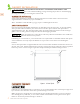
INSTALLATION OF DISPENSING EQUIPMENT (continued) EN Dispensing Head Apply silicone to bottom flange Faucet Lead Air Distributor Regulator Flange Sleeve All hose connections use worm-drive hose clamps (view enlarged to verify) Beer Connection Keg Keg Coupler NOTE: Image does not accurately reflect positions of the different elements within the unit. Postions and hose lengths shown are to clearly illustrate proper connection methods only.
INSTALLATION OF DISPENSING EQUIPMENT (continued) 1. Locate the dispensing head , black beer line(s), and hose clamp(s). Slide one end of each beer line onto the stainless steel tubes which protrude out the bottom of the dispensing head and clamp tight. EN 2. Remove transit tape with a utility knife around the hole in the top of the unit from both inside and outside of the cabinet. Gently punch out foam w/screwdriver and remove. Insert the beer line(s) through the hole in the countertop.
INSTALLATION OF DISPENSING EQUIPMENT (continued) 4. Install the Air Scoop Kit. Start by removing the upper set of screws located above the fan on the back wall of the cabinet. EN 5. Assemble components from the kit as follows – Insert black snap bushing into air scoop mounting bracket, then insert one end of the air snorkel through the snap bushing. A zip-tie can be inserted behind the mounting bracket to keep the tube in place. 6.
INSTALLATION OF DISPENSING EQUIPMENT (continued) 7. If installing a two faucet system, a CO2 manifold will need to be installed. Locate the red CO2 lines, CO2 manifold and a #10 x 1/2” sheet metal screw. Slide one end of each hose onto the barbed fittings on the manifold and clamp. On the left rear side wall of the beer compartment there is a double row of screws which run vertically. Remove one of the two top screws and discard.
INSTALLATION OF DISPENSING EQUIPMENT (continued) 10. On the right rear sidewall there is a double column of screws. Remove the left screw. Locate the safety chain and a #10 x 1/2” sheet metal screw from the parts bag. Insert the screw through the closed end link of the chain and tighten in the vacant screw hole. The chain can now be used to secure the CO2 cylinder with “S” hook, preventing damage to the regulator. EN 11. CO2 cylinders are shipped empty and must be filled prior to use.
INSTALLATION OF DISPENSING EQUIPMENT (continued) 13. Before tapping a keg, make sure the beer faucet is closed. EN To tap a keg, insert the coupler into the neck of the barrel. Turn the coupler clockwise until it stops (about an 1/8 turn), then push down on the top of the coupler and again turn clockwise until it stops. Your barrel is now tapped. Open the CO2 valve on the regulator as well as the valve on the manifold if used.
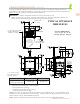
CONNECTING THE REGULATOR TO THE CO2 CYLINDER (continued) NUT FOR CO2 CYLINDER FITTING EN OUTLET PRESSURE REGULATOR ADJUSTMENT KNOB OR SCREW CYLINDER PRESSURE CYLINDER VALVE CO2 CYLINDER SHUT-OFF VALVE OFF POSITION BARB FITTING FOR RED AIR HOSE 1. Remove the blue plug from the regulator fitting, but do not remove the carbonic washer. 2. Screw regulator onto gas cylinder valve. Tighten the nut with a wrench until vertically straight.
DISPOSAL DANGER Risk of child entrapment. Before you throw away your old refrigerator or freezer: • Take off the door. • Leave the shelves in place so that children may not easily climb inside. • Do not allow children to play inside, on, or around the appliance. EN Risk of fire or explosion. Please dispose the appliance according to federal or local regulations for its flammable refrigerant and blowing gas.
TABLES DES MATIERES 1 2 2 3 3 3 5 8 10 16 18 FR DÉFINITIONS DE SÉCURITÉ NUMÉROS DE MODÈLE DISPOSITION DES BARILS PLAQUE SIGNALÉTIQUE RESPECT DE LA RÉGLEMENTATION ET DES CODES EN VIGUEUR SÉCURITÉ INSTALLATION DE L’ARMOIRE INFORMATION SUR LA PORTE INSTALLATION DE L’ÉQUIPEMENT DE DISTRIBUTION RACCORDEMENT DU RÉGULATEUR AU CYLINDRE DE CO2 ÉLIMINATION LISEZ ATTENTIVEMENT ET COMPLÈTEMENT CES INSTRUCTIONS AVANT D’INSTALLER OU D’UTILISER VOTRE APPAREIL AFIN DE RÉDUIRE LES RISQUES D’INCENDIE, DE BRÛLURE OU D’AUTR
DÉFINITIONS DE SÉCURITÉ (suite) AVIS Ce produit contient de la mousse isolante thermique utilisant l’agent gonflant R-611 (Formiate de Méthyle). La mousse de ce produit ne contient pas de HFC, CFC ou HCFC. Tous les modèles couverts dans ce manuel sont fabriqués à l’aide du réfrigérant R600a (Isobutane). Le R600a est un hydrocarbure.
PLAQUE SIGNALÉTIQUE La plaque signalétique contient des informations importantes sur votre appareil Hestan, telles que le modèle et le numéro de série, ainsi que des informations sur le réfrigérant si un entretien est nécessaire. PLAQUE SIGNALÉTIQUE FR La plaque signalétique est fixée sur le dessus intérieur de la caisse. RESPECT DE LA RÉGLEMENTATION ET DES CODES EN VIGUEUR L’installation de cet appareil doit être effectuée conformément aux codes locaux.
SÉCURITÉ (suite) PLOMBERIE Mis à part les connexions au robinet de bière et au baril (voir page 10), aucune autre connexion de plomberie n’est requise. Les condensats du serpentin de refroidissement s’évaporent automatiquement à travers un bac à condensats situé dans la section de condensation de l’unité. DANGER FR GAZ HAUTE PRESSION • • Gardez la cylindre de CO2 à l’abri de la chaleur. Le disque de rupture est ventilé à 122°F [50°C] max.
SÉCURITÉ (suite) DANGER Ne stockez pas de liquides inflammables (c’est-à-dire d’essence ou de liquide à briquet) ou de vapeurs à proximité de l’appareil pour éviter un incendie. INFORMATIONS GÉNÉRALES SUPPLÉMENTAIRES Toutes les instructions électriques supposent que la prise est située à 4 - 10 po [10 - 25 cm] au-dessus de la surface du sol. Le plancher doit être de niveau dans la zone d’installation.
INSTALLATION DE L’ARMOIRE (suite) PRÉPARER L’ESPACE Si l’unité doit être installée sous un plan de travail, il est recommandé que le plan de travail soit soutenu par une structure autre que l’unité elle-même pour éviter d’endommager l’unité. Assurez-vous que le plancher sous l’unité est au même niveau que le plancher fini environnant. Protégez un plancher fini avec du contreplaqué, du carton ou tout autre matériau approprié avant de déplacer l’unité en place.
INSTALLATION DE L’ARMOIRE (suite) 2. Vérifiez que les éléments suivants sont de niveau et d’équerre: • Ouverture frontale et intérieure • Ouverture d’installation et surface au sol • Bord avant inférieur du comptoir REMARQUE: Pour qu’une porte s’ouvre correctement, la porte doit s’ouvrir d’au moins 90°. Utiliser un pièce d’obturation d’au moins 3 po [7,6 cm] dans les installations en coin pour assurer une ouverture complète à 90°.
INSTALLATION DE L’ARMOIRE (suite) INSTALLATION DU COUVERCLE DE GRILLE AVANT Une fois l’unité en place, installez le couvercle de la grille avant à persiennes. Fixez le couvercle en enclenchant le pêne dans le loquet de l’unité (Figure 3). La grille de ventilation doit être retirée pour l’entretien de l’unité. Le sol ne peut pas interférer avec l’enlèvement, et les sections persiennes ne doit pas être couvert ou obstrué.
INFORMATION SUR LA PORTE (suite) INSTALLATION DE SERRURE DE PORT Support de Montage Des matériaux et équipements de travail du bois appropriés doivent être utilisés pour éviter des dommages ou des erreurs de fabrication. REMARQUE: Les informations d’installation du verrou sont disponibles sur les dessins de gabarit mentionnés ci-dessus. Faites attention en choisissant le modèle correct pour votre modèle spécifique.
INSTALLATION DE L’ÉQUIPEMENT DE DISTRIBUTION AVANT L’INSTALLATION Ouvrez la boîte du kit de distribution et familiarisez-vous avec ses composants. Si la tête de distribution doit être montée sur un plan de travail directement au-dessus de l’armoire réfrigérée, faites percer le plan de travail en utilisant le modèle imprimé dans l’annexe de ce manuel. FR Assurez-vous que le trou d’accès dans l’armoire réfrigérée est aligné avec les trous du comptoir. Retirez tout obstacle du trou d’accès du réfrigérateur.
INSTALLATION DE L’ÉQUIPEMENT DE DISTRIBUTION (suite) FR Tête de distribution Appliquer du silicone sur la bride inférieure Fil de robinet Distributeur d'air Regulateur Manchon à bride Tous les raccords de tuyaux utilisent des colliers de serrage à vis sans fin (vue agrandie pour vérifier) Connexion de bière Baril Coupleur de valve de baril. REMARQUE: l'image ne reflète pas avec précision les positions du différents éléments au sein de l'unité.
INSTALLATION DE L’ÉQUIPEMENT DE DISTRIBUTION (suite) 1. Localisez la tête de distribution, les conduites de bière noire et les colliers de serrage. Faites glisser une extrémité de chaque ligne de bière sur les tubes en acier inoxydable qui dépassent le bas de la tête de distribution et serrez fermement. FR 2. Retirez le ruban de transport avec un couteau utilitaire autour du trou dans le haut de l’unité de l’intérieur et de l’extérieur de l’armoire.
INSTALLATION DE L’ÉQUIPEMENT DE DISTRIBUTION (suite) 4. Installez le kit prise d’air. Commencez par retirer le jeu de vis supérieur situé au-dessus du ventilateur sur la paroi arrière de l’armoire. FR 5. Assemblez les composants du kit comme suit - Insérez la bague de pression noire dans le support de montage de la prise d’air, puis insérez une extrémité du tuba à air à travers la bague de pression. Un serre-câble peut être inséré derrière le support de montage pour maintenir le tube en place. 6.
INSTALLATION DE L’ÉQUIPEMENT DE DISTRIBUTION (suite) 7. Si vous installez un système à deux robinets, un collecteur de CO2 devra être installé. Localisez les lignes de CO2 rouges, le collecteur de CO2 et une vis à tôle #10 x 1/2 po. Faites glisser une extrémité de chaque tuyau sur les raccords cannelés du collecteur et fixez-les. Sur la paroi latérale arrière gauche du compartiment à bière se trouve une double colonne de vis qui sont montées verticalement. Retirez l’une des deux vis supérieures et jetez-la.
INSTALLATION DE L’ÉQUIPEMENT DE DISTRIBUTION (suite) 10. Sur la paroi latérale arrière droite se trouve une double colonne de vis. Retirez la vis gauche. Localisez la chaîne de sécurité et une vis à tôle #10 x 1/2 po du sac de pièces. Insérez la vis à travers le maillon d’extrémité fermé de la chaîne et serrez dans le trou de vis vide. La chaîne peut maintenant être utilisée pour fixer la cylindre de CO2 avec un crochet en «S», ce qui évite d’endommager le régulateur. FR 11.
INSTALLATION DE L’ÉQUIPEMENT DE DISTRIBUTION (suite) 13. Avant de percer un baril, assurez-vous que le robinet de bière est fermé. Pour percer un baril, insérez le coupleur dans le col du baril. Tournez le coupleur dans le sens anti-horaire jusqu’à ce qu’il s’arrête (environ 1/8 de tour), puis appuyez sur le haut du coupleur et tournez à nouveau dans le sens anti-horaire jusqu’à ce qu’il s’arrête. Votre baril est maintenant percé.
RACCORDEMENT DU RÉGULATEUR AU CYLINDRE DE CO2 (suite) PRESSION DE SORTIE FR ECROU POUR RACCORD DE RESERVOIR CO2 BOUTON OU VIS DE RÉGLAGE DU RÉGULATEUR PRESSION DU RÉSERVOIR ROBINET DE RÉSERVOIR RÉSERVOIR CO2 POSITION D'ARRÊT DE LA VANNE D'ARRÊT RACCORD CANNELÉ POUR TUYAU D'AIR ROUGE 1. Retirez le bouchon bleu du raccord du régulateur, mais ne retirez pas la rondelle carbonique. 2. Visser le régulateur sur la valve de la cylindre de gaz.
ÉLIMINATION DANGER Risque de coincement de l’enfant. Avant de jeter votre ancien réfrigérateur: • Enlevez les portes. • Laissez les étagères en place afn que les enfants ne puissent pas facilement grimper à l’intérieur. • Ne laissez pas les enfants jouer dans, sur ou autour de l’appareil. FR Risque d’incendie ou d’explosion. Veuillez éliminer l’appareil conformément aux réglementations fédérales ou locales pour son réfrigérant inflammable et son gaz de soufflage.
FR THIS PAGE LEFT INTENTIONALLY BLANK CETTE PAGE EST INTENTIONNELLEMENT VIDE 19 ©2021 Hestan Commercial Corporation
APPENDIX / ANNEXE MOUNTING HOLE TEMPLATE FOR DRAFT ARMS GABARIT DE TROU DE MONTAGE POUR TÊTE DE DISTRIBUTEUR FR ATTENTION INSTALLERS 4-1/2” DIAM. STANDARD FAUCET BASE (BASE DE ROBINET STANDARD) THIS IS A FULL SIZE TEMPLATE. PLEASE CONFIRM THAT DRAWING DIMENSIONS ARE TO SCALE PRIOR TO INSTALLATION. 1-3/8” 1-3/8” 2-9/16” DIAM. HOLE (TROU) 1-3/8” 1-3/8” 3/32” DIAM. HOLE (TROU) (4) REQ. #8 X 1-1/4” LONG SCREWS (VIS) (4) REQ. ATTENTION AUX INSTALLATEURS CECI EST UN GABARIT DE GRANDE TAILLE.
RETAIN THIS MANUAL FOR FUTURE REFERENCE CONSERVEZ CE MANUEL POUR UNE RÉFÉRENCE FUTURE Hestan Commercial Corporation 3375 E. La Palma Ave.