INDOOR COOKING Radiant Cooktop KEC Installation Manual
IF THE INFORMATION IN THIS MANUAL IS NOT FOLLOWED EXACTLY, A FIRE OR EXPLOSION MAY RESULT CAUSING PROPERTY DAMAGE, PERSONAL INJURY, OR DEATH. Do not store or use gasoline or other flammable vapors and liquids in the vicinity of this or any other appliance. Installation and service must be performed by a qualified installer or service agency. DO NOT REPAIR, REPLACE OR REMOVE ANY PART OF THE APPLIANCE UNLESS SPECIFICALLY RECOMMENDED IN THE MANUAL.
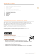
TABLE OF CONTENTS 1 2 2 2 3 5 8 10 11 11 SAFETY PRECAUTIONS - BEFORE YOU BEGIN MODEL NUMBERS RATING LABEL REGULATORY / CODE REQUIREMENTS CUTOUT DIMENSIONS AND REQUIREMENTS COOKTOP INSTALLATION ELECTRICAL CONNECTIONS FINAL SETUP PARTS LIST SERVICE EN SAFETY PRECAUTIONS - BEFORE YOU BEGIN When properly cared for, your Hestan appliance will provide safe, reliable service for many years. When using this appliance, basic safety practices must be followed as outlined below.
MODEL NUMBERS EN MODEL NO. DESCRIPTION CIRCUIT BREAKER REQ’D KEC 30 30” Radiant Cooktop 40 Amp KEC 30 30” Radiant Cooktop 50 Amp RATING LABEL The rating label contains important information about your Hestan appliance such as the model and serial number, electrical rating and the minimum installation clearances. The rating label is located on the bottom of the cooktop. If service is necessary, contact Hestan Customer Care with the model and serial number information shown on the label.
CUTOUT DIMENSIONS AND REQUIREMENTS 30’’ 30” 3/8 [77.1 cm] EN 21” 3/16 [53.8 cm] 3” 1/8 [7.9 cm] 36” 3/16 [91.9 cm] 36’’ 21” 3/16 [53.8 cm] 3” 1/8 [7.9 cm] Figure 1. SLOT FOR CABLE ROUTING 3-1/2” [9 cm] 2-1/2” [6.5 cm] CUTOUT DIMENSION LENGTH OF CUT A LENGTH OF CUT SEE NOTE 1-1/2” [3.8CM] MIN CLEARANCE R B FROM EDGE OF CUTOUT AND FRONT EDGE OF COUNTERTOP 2-1/2” [6.5 cm] 1-1/4” [3.2 cm] Canadian 2-1/4” [5.7cm] US Figure 2.
CUTOUT DIMENSIONS AND REQUIREMENTS (CONT.) CUTOUT REQUIREMENTS G EN WALL COVERING CABINETS, AND COUNTERTOP MUST WITHSTAND HEAT UP TO 200°F [93°C] C E F D Figure 3. Cutout dimensions and requirements CUTOUT WIDTH A B C D E 18” [45.7 cm] min Height from countertop to nearest cabinet on either side of unit 30” [76.2 cm] min. [see note*] Clearance from countertop to unprotected overhead surface 30” [76.2cm] 28-11/16” [72.9 cm] 28 15/16” [73.5 cm] 19-1/4” [49.0 cm] 19-5/8” [49.8 cm] 30” [76.
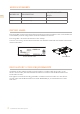
COOKTOP INSTALLATION Excessive Weight Hazard Use two or more people to move and install cooktop. Failure to do so can result in back or other injury. Cut Hazard Beware of sharp edges. Use the polystyrene ends when carrying the product. Failure to use caution could result in minor injury or cuts. Step 1 Remove packaging materials and literature package from the cooktop before beginning installation. Remove Installation Manual from literature pack and read them carefully before you begin.
COOKTOP INSTALLATION (CONT.) Step 2 Place a towel or table cloth onto the counter top. Lay the cooktop upside down onto the protected surface. EN Step 4 Insert the cooktop centered into the cutout opening. Make sure the front edge of the counter top is parallel to the cooktop. Make final check that all required clearences are met. Figure 6 Step 3 A foam tape is provided to seal the cooktop edges to the countertop. Apply tape approximately 1/16” (1.
COOKTOP INSTALLATION (CONT.) 12” [30.5cm] MIN FROM BOTTOM OF COUNTERTOP AND ADJACENT CABINET (RIGHT SIDE) • • • EN THE CONDUIT IS 3 FEET LONG The junction box must be located where it will allow sufficient slack in the conduit for serviceability. For solid surface material installations such as Surel™ and Corian®, consult with solid surface manufacturer. Apply heat reflective tape such as Scotch® Aluminum Foil Tape #425 or #427 around the cutout so that it folds over on the top and sides.
ELECTRICAL CONNECTIONS EN Disconnect power before servicing the product. Failure to do so could result in death or electrical shock . General information The models may be powered at 240V or 208V. This cooktop does not require a neutral connection. If the cooktop is to be completely enclosed in a cabinet, feed the cooktop cable through the opening in the cabinet. Make the electrical connection following the appropriate steps for your installation.
ELECTRICAL CONNECTIONS (CONT.) Recommended Minimum kW Rating on serial plate Circuit protection in amperes Wire size (AWG) 0-4.8 20 12 4.9-6.9 30 10 7.0-9.9 40 8 10.0-11.9 50 8 12.0-14.9 60 6 EN Be sure your appliance is properly installed and grounded by a qualified technician. Ask your dealer to recommend a qualified technician or an authorized repair service. This cooktop does not require a neutral connection.
FINAL SETUP CLEANUP, VERIFY POWER Remove any final packaging materials and protective film from all exterior areas. EN Check the electrical requirements for the correct electrical supply and that the cooktop is properly grounded. Check power at the junction box wires using a voltmeter having a range of 0-250 VAC. • • A 240 Volt supply should read 220 to 240 Volts between the black and red wires (Line to Line). A 208 Volt supply should read 190 to 208 Volts between the black and red wires.
PARTS LIST Please visit the Hestan website to access the parts list for your Hestan Indoor product: www.hestanhome.com. EN SERVICE All warranty and non-warranty repairs should be performed by qualified service personnel. To locate an authorized service agent in your zone, contact your Hestan dealer, local representative, or the manufacturer. Before you call, please have the model number and serial number information ready. Hestan Commercial Corporation 3375 E.
L’INOBSERVATION DES INFORMATIONS DONNÉES DANS CE MANUEL PEUT ENTRAÎNER UN INCENDIE OU UNE EXPLOSION DE NATURE À CAUSER DES DÉGÂTS MATÉRIELS ET DES BLESSURES GRAVES, VOIRE MORTELLES. Ne pas entreposer ni utiliser de I’essence ni d’autres vapeurs ou liquides inflammables dans Ie voisinage de l’apparell, ni de tout autre appareil. L’installation et l’entretien doivent être effectués par un installateur qualifié, ou une agence de service.
TABLES DES MATIERES 1 2 2 2 3 5 8 10 11 11 PRÉCAUTIONS DE SÉCURITÉ - AVANT DE COMMENCER NUMÉROS DE MODÈLE PLAQUE SIGNALÉTIQUE RESPECT DE LA RÉGLEMENTATION ET DES CODES EN VIGUEUR DIMENSIONS DU PRODUIT ET EXIGENCES DE DÉCOUPE INSTALLATION DE LA TABLE DE CUISSON CONNEXIONS ELECTRIQUES CONFIGURATION FINAL LISTE DES PIÈCES SERVICE FR PRÉCAUTIONS DE SÉCURITÉ - AVANT DE COMMENCER S’il est bien entretenu, cet appariel Hestan procurera un service sûr et fiable pendant de nombreuses années.
NUMÉROS DE MODÈLE MODÈLES DES TABLE DE CUISSON FR MODEL NO. DESCRIPTION DISJONCTEUR REQUIS KEC 30 Table De Cuisson Électrique, 30 po 40 Ampères KEC 36 Table De Cuisson Électrique, 36 po 50 Ampères PLAQUE SIGNALÉTIQUE La plaque signalétique donne des informations importantes sur cet appareil Hestan telles que les numéros de série et de modèle et les dégagements minima d’installation. La plaque signalétique se trouve sous l’unité.
DIMENSIONS DU PRODUIT ET EXIGENCES DE DÉCOUPE 30’’ 30” 3/8 (77,1 cm) 21” 3/16 (53,8 cm) FR 3” 1/8 (7,9 cm) 36” 3/16 (91,9 cm) 36’’ 21” 3/16 (53,8 cm) 3” 1/8 (7,9 cm) Figure 1. DIMENSION DE LA DÉCOUPE SLOT POUR CABLES 3-1/2” (9 cm) 2-1/2” (6.5 cm) LONGUEUR DE DÉCOUPE A 1-1/2” (3.8CM) ESPACE MINIMUM LONGUEUR DE DÉCOUPE VOIR NOTE R B DU BORD DE LA DÉCOUPE AU BORD ANTÉRIEUR DU PLAN DE TRAVAIL 2-1/2” (6.5 cm) 1-1/4” (3,2 cm) Canada 2-1/4” (5,7cm) US Figure 2.
DIMENSIONS DU PRODUIT ET EXIGENCES DE DÉCOUPE (SUITE) DISPOSITIONS POUR LA DÉCOUPE G LES REVETEMENTS DES MEUBLES ET LE PLAN DE TRAVAIL DOIVENT RESISTER A UNE CHALEUR DE 200°F [93°C] FR C E F D Figure 3.
INSTALLATION DE LA TABLE DE CUISSON PRÉCAUTION Risque du fait du poids excessif Soyez à deux personnes ou plus pour porter et installer la table de cuisson. Sinon, vous risquez de vous blesser au dos ou de subir d’autres blessures. Risque de coupure Méfiez-vous des bords tranchants et des extrémités du polystyrène lorsque vous portez le produit. Sinon, vous risquez de vous couper ou de vous faire légèrement mal. Toujours consulter le fabricant du plan de travail pour les instructions spécifiques.
INSTALLATION DE LA TABLE DE CUISSON (SUITE) Étape 2 Placez un torchon ou une serviette sur le plan de travail. Posez la table de cuisson du haut vers le bas dans la surface protégée. FR Étape 4 Insérez la table de cuisson au centre de l'ouverture de la découpe. Assurez-vous que le bord avant du comptoir est parallèle à la surface de cuisson. Faire une dernière vérification pour s'assurer que toutes les distances de dégagement requises sont respectées.
INSTALLATION DE LA TABLE DE CUISSON (SUITE) AVIS LE CONDUIT A UNE LONGUEUR DE 3 PIEDS la boîte de jonction, doit être dans un endroit qui permette que le conduit pour l’entretien ait suffi-samment de jeu. FR AVIS • • Pour les installations de matériau solide comme le Surei™ et le Corian ®, consultez le fabricant de surface solide.
CONNEXIONS ELECTRIQUES Débranchez l’électricité avant de mettre en service le produit. Sinon, vous risquez de vous tuer ou de vous électrocuter . FR Informations générales Le conduit flexible conduit (fourni) de 3 pieds (100 cm) situé à l’arrière à droite sous le caisson de la table de cuisson doit être connecté directement à la boîte de jonction. Ne coupez pas le conduit. Un raccord de conduit U.
CONNEXIONS ELECTRIQUES (SUITE) Minimum recommandé Caractéristiques des kW sur plaques de série Protection de circuit en ampères Taille de câble (AWG) 0-4.8 20 12 4.9-6.9 30 10 7.0-9.9 40 8 10.0-11.9 50 8 12.0-14.9 60 6 FR Assurez-vous que votre installation est correctement installée et branchée par un technicien qualifié. Demandez à votre revendeur un technicien qualifié ou un service de réparation agréé. Cette table de cuisson n’exige pas de connexion neutre.
CONFIGURATION FINAL NETTOYAGE, VÉRIFIEZ LA PUISSANCE Enlever tout matériau d’emballage final et film de protection de toutes les zones extérieures. FR Vérifiez les exigences électriques pour l’alimentation électrique correcte et que la table de cuisson est correctement mise à la terre. TRIPLE DUAL TIME Vérifiez l’alimentation aux fils de la boîte de jonction à l’aide d’un voltmètre ayant une plage de 0-250 VCA.
LISTE DES PIÈCES Visiter le site Web Hestan pour consulter la liste des pièces de ce produit: www.hestanhome.com. SERVICE FR Toutes les réparations dans le cadre ou en dehors de la garantie doivent être effectuées par du personnel d’entretien qualifié. Pour localiser un réparateur agréé dans la région, s’adresser au concessionnaire Hestan, au représentant local ou à l’usine. Avant d’appeler, veiller à avoir les numéros de modèle et de série à portée de la main. Hestan Commercial Products 3375 E.
Cette page a été intentionnellement laissée vierge
RETAIN THIS MANUAL FOR FUTURE REFERENCE CONSERVEZ CE MANUEL POUR UNE RÉFÉRENCE FUTURE Hestan Commercial Corporation 3375 E.