INDOOR COOKING Smart Induction Cooktop KICS Installation Manual
EN IF THE INFORMATION IN THIS MANUAL IS NOT FOLLOWED EXACTLY, A FIRE OR EXPLOSION MAY RESULT CAUSING PROPERTY DAMAGE, PERSONAL INJURY, OR DEATH. Do not store or use gasoline or other flammable vapors and liquids in the vicinity of this or any other appliance. Installation and service must be performed by a qualified installer or service agency. DO NOT REPAIR, REPLACE OR REMOVE ANY PART OF THE APPLIANCE UNLESS SPECIFICALLY RECOMMENDED IN THE MANUAL.
TABLE OF CONTENTS 1 2 2 2 3 6 9 11 12 12 SAFETY PRECAUTIONS - BEFORE YOU BEGIN MODEL NUMBERS RATING LABEL REGULATORY / CODE REQUIREMENTS CUTOUT DIMENSIONS AND REQUIREMENTS COOKTOP INSTALLATION ELECTRICAL CONNECTIONS FINAL SETUP PARTS LIST SERVICE EN SAFETY PRECAUTIONS - BEFORE YOU BEGIN When properly cared for, your Hestan appliance will provide safe, reliable service for many years. When using this appliance, basic safety practices must be followed as outlined below.
MODEL NUMBERS COOKTOP MODELS EN MODEL NO. DESCRIPTION CIRCUIT BREAKER REQUIRED KICS30 30” Smart Induction Cooktop 40 Amp KICS36 36” Smart Induction Cooktop 50 Amp RATING LABEL The rating label contains important information about your Hestan appliance such as the model and serial number, electrical rating and the minimum installation clearances. The rating label is located on the bottom of the cooktop.
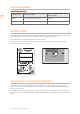
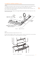
CUTOUT DIMENSIONS AND REQUIREMENTS CABINET REQUIREMENTS To eliminate the risk of burns or fire by reaching over heated surface units, cabinet storage units located above the surface units should be avoided. If cabinet storage is to be provided, the risk can be reduced by installing a range hood that projects horizontally a minimum of 5 inches [12.7 cm] beyond the bottom of the cabinets. E WALL COVERING, CABINETS, AND COUNTERTOP MUST WITHSTAND HEAT UP TO 200°F [93ºC] C A B D Figure 2.
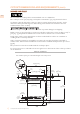
CUTOUT DIMENSIONS AND REQUIREMENTS (CONT.) BEFORE YOU START EN Do not install the cooktop above an unventilated oven or a dishwasher. The cooktop is 2-1/2” [6.4 cm] deep, and requires a minimum 1” [2.5 cm] clearance below it. If a drawer is directly below the cooktop, it and its contents must be heat resistant. Such a drawer should be placed/arranged so that nothing can be drawn from the drawer into the ventilation fans of the cooktop.
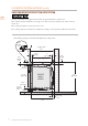
CUTOUT DIMENSIONS AND REQUIREMENTS (CONT.) Model W KICS30 30-5/16” [77.0 cm] KICS36 36-5/32” [91.8 cm] EN W 2 [55.21- ¾” cm] 3/8” [9.5 mm] 2-½” Figure 3. Cooktop dimensions Model F KICS30 28-3/8” [72 cm] KICS36 34-1/4” [87 cm] HOLE FOR POWER CABLE F [6.4 cm] MIN. CLEARANCE 2” [5.1 cm] 3-½” [8.9 cm] min. depth 19-¼” [48,9 cm] URE LOS C N E TOM BOT NAL) IO (OPT Figure 4.
COOKTOP INSTALLATION EN EXCESSIVE WEIGHT HAZARD Use two or more people to move and install cooktop. Failure to do so can result in back or other injury. CUT HAZARD Beware of sharp edges. Wear protective gloves or use the polystyrene ends when carrying the product. Failure to use caution could result in minor injury or cuts. Always consult the countertop manufacturer for specific instructions. Ensure the countertop is square and level and ensure no structural members interfere with space requirements.
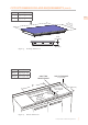
COOKTOP INSTALLATION (CONT.) STEP 3 A foam tape is provided to seal the cooktop to the countertop. Apply tape to the underside of the cooktop glass between the body of the cooktop and the inner edge of the metal frame. There should be about 3/32” [2 mm] between the edge of the tape and the edge of the glass. Use tape around the entire glass perimeter. The tape will retain the cooktop and seal against leaks into the cabinet. Trim the tape ends so that they meet with no gaps.
COOKTOP INSTALLATION (CONT.) COOKTOP INSTALLATION OVER A SINGLE OVEN EN Use the countertop opening dimensions that are given with these instructions. The cooktop may be installed over a single oven. The oven must exhaust out of the cooktop enclosure. The cooktop should be centered over the oven. The cooktop and the oven must be installed according to each specific installation instruction. * The ventilation opening is to extend the full length of the cooktop cutout.
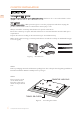
ELECTRICAL CONNECTIONS Disconnect power before servicing the product. Failure to do so could result in death or electrical shock. EN Your cooktop can use 200-240V at 50 or 60 Hz. The connection leads are 3x8 AWG copper. This cooktop does not require a neutral connection. If the cooktop is to be completely enclosed in a cabinet, feed the cooktop cable through the opening in the cabinet. Make the electrical connection following the appropriate steps for your installation.
ELECTRICAL CONNECTIONS (CONT.) This appliance is manufactured with a green ground wire connected to the cooktop chassis. After making sure that the power has been turned off, connect the flexible conduit from the cooktop to the junction box using a U.L. listed conduit connector. The instructions provided below present the most common way of connecting the cooktop. Your local codes and ordinances, of course, take precedence over these instructions.
FINAL SETUP CLEANUP, VERIFY POWER Remove any final packaging materials and protective film from all exterior areas. Check the electrical requirements for the correct electrical supply and that the cooktop is properly grounded. Check power at the junction box wires using a voltmeter having a range of 0-250 VAC. • • A 240 Volt supply should read 220 to 240 Volts between the black and red wires (Line to Line). A 208 Volt supply should read 190 to 208 Volts between the black and red wires.
PARTS LIST Please visit the Hestan website to access the parts list for your Hestan Indoor product: www.hestanhome.com. EN SERVICE All warranty and non-warranty repairs should be performed by qualified service personnel. To locate an authorized service agent in your zone, contact your Hestan dealer, local representative, or Hestan. Before you call, please have the model number and serial number information ready. Hestan Commercial Corporation 3375 E.
FR L’INOBSERVATION DES INFORMATIONS DONNÉES DANS CE MANUEL PEUT ENTRAÎNER UN INCENDIE OU UNE EXPLOSION DE NATURE À CAUSER DES DÉGÂTS MATÉRIELS ET DES BLESSURES GRAVES, VOIRE MORTELLES. Ne pas entreposer ni utiliser de I’essence ni d’autres vapeurs ou liquides inflammables dans Ie voisinage de l’apparell, ni de tout autre appareil. L’installation et l’entretien doivent être effectués par un installateur qualifié, ou une agence de service.
TABLES DES MATIERES 1 2 2 2 3 6 9 11 12 12 FR PRÉCAUTIONS DE SÉCURITÉ - AVANT DE COMMENCER NUMÉROS DE MODÈLE PLAQUE SIGNALÉTIQUE RESPECT DE LA RÉGLEMENTATION ET DES CODES EN VIGUEUR DIMENSIONS DU PRODUIT ET EXIGENCES DE DÉCOUPE INSTALLATION DE LA TABLE DE CUISSON CONNEXIONS ELECTRIQUES CONFIGURATION FINAL LISTE DES PIÈCES SERVICE PRÉCAUTIONS DE SÉCURITÉ - AVANT DE COMMENCER Lorsqu’elle est correctement entretenue, votre appareil Hestan fournira un service sûr et fiable pendant de nombreuses années.
NUMÉROS DE MODÈLE MODÈLES DE TABLE DE CUISSON NO. MODÈLE DESCRIPTION DISJONCTEUR REQUIS KICS30 Table de cuisson à induction Smart de 30 po 40 Ampères KICS36 Table de cuisson à induction Smart de 36 po 50 Ampères FR PLAQUE SIGNALÉTIQUE La plaque signalétique fournit des informations importantes sur cet appareil Hestan telles que le numéro de série, le numéro de modèle et la classification électrique. La plaque signalétique est située sous l’unité.
DIMENSIONS DU PRODUIT ET EXIGENCES DE DÉCOUPE EXIGENCES DE CABINET Pour éliminer les risques de brûlures ou d’incendie en atteignant les unités de surface chauffées, les unités de rangement des armoires situées au-dessus des unités de surface doivent être évitées. Si le rangement de l’armoire doit être fourni, le risque peut être réduit en installant un capot qui dépasse horizontalement d’au moins 5 po [12,7 cm] du fond des armoires.
DIMENSIONS DU PRODUIT ET EXIGENCES DE DÉCOUPE (SUITE) AVANT DE COMMENCER FR N’installez pas la table de cuisson au-dessus d’un four non ventilé ou d’un lave-vaisselle. La table de cuisson mesure 2-1/2 po [6,4 cm] de profondeur et nécessite un dégagement d’au moins 1 po [2,5 cm] en dessous. Si un tiroir est directement sous la table de cuisson, elle doit être résistante à la chaleur.
DIMENSIONS DU PRODUIT ET EXIGENCES DE DÉCOUPE (SUITE) Modèle FR W KICS30 30-5/16 po [77 cm] KICS36 36-5/32 po [91,8 cm] W 2 [55.21- ¾ po cm] 3/8 po [9.5 mm] 2-½ po Figure 3. Dimensions de la Table de Cuisson Modèle F KICS30 28-3/8 po [72 cm] KICS36 34-1/4 po [87 cm] HOLE FOR POWER CABLE F 5 Dimensions de découpe ©2019 Hestan Commercial Corporation MIN. CLEARANCE 2” [5.1 cm] 3-½” [8.9 cm] min. depth URE LOS C N E TOM BOT NAL) IO (OPT Figure 4. [6.
INSTALLATION DE LA TABLE DE CUISSON FR RISQUE DU FAIT DU POIDS EXCESSIF Soyez à deux personnes ou plus pour porter et installer la table de cuisson. Sinon, vous risquez de vous blesser au dos ou de subir d’autres blessures. RISQUE DE COUPURE Attention aux des bords tranchants. Portez des gants de protection ou utilisez les extrémités en polystyrène lorsque vous transportez le produit. Ne pas faire preuve de prudence peut entraîner des blessures légères ou des coupures.
INSTALLATION DE LA TABLE DE CUISSON (SUITE) ÉTAPE 3 Un ruban adhésif est fourni pour sceller la table de cuisson au comptoir. Appliquez cette adhésif sur le dessous de la vitre de la table de cuisson entre le corps de la table de cuisson et le bord intérieur du cadre. FR Il devrait y avoir environ 3/32 po [2 mm] entre le bord du ruban et le bord du verre. Utilisez le ruban autour du périmètre de verre entier. Le ruban adhésif fourni avec l’appareil permet d’éviter toute infiltration dans le meuble.
INSTALLATION DE LA TABLE DE CUISSON (SUITE) INSTALLATION SUR UN FOUR ENCASTRÉ SIMPLE FR Utilisez les dimensions d’ouverture du comptoir fournies avec ces instructions. La table de cuisson peut être installée sur un seul four. Le four doit sortir de l’enceinte de la table de cuisson. La table de cuisson doit être centrée sur le four. La table de cuisson et le four doivent être installés conformément à chaque instruction d’installation spécifique.
CONNEXIONS ELECTRIQUES FR Débranchez l’alimentation avant d’effectuer l’entretien du produit. Ne pas le faire pourrait entraîner la mort ou un choc électrique. Votre table de cuisson peut utiliser 200-240V à 50 ou 60 Hz. Les fils de connexion sont en cuivre 3x8 AWG. Cette table de cuisson ne nécessite pas de connexion neutre. Si la table de cuisson doit être complètement enfermée dans une armoire, introduisez le câble de la table de cuisson dans l’ouverture de l’armoire.
CONNEXIONS ELECTRIQUES (SUITE) Cet appareil est fabriqué avec un conducteur de terre vert connecté au châssis de la table de cuisson. Après vous être assuré que l’appareil était hors tension, branchez le conduit flexible depuis le table de cuisson à la boîte de jonction en utilisant un connecteur de conduit U.L. listé. Les instructions fournies ci-dessous représentent la manière la plus commune de brancher un table de cuisson. Bien entendu, vos codes et ordonnances locaux ont préséance sur ces instructions.
CONFIGURATION FINAL NETTOYAGE, VÉRIFIEZ LA PUISSANCE Retirez tous les matériaux d’emballage final et le film protecteur de toutes les zones extérieures. FR Vérifiez les exigences électriques pour l’alimentation électrique correcte et que la table de cuisson est correctement mise à la terre. Vérifiez l’alimentation des fils de la boîte de jonction à l’aide d’un voltmètre de 0-250 VCA. • Une alimentation de 240 volts devrait lire entre 220 et 240 volts entre les fils noir et rouge (ligne à ligne).
LISTE DES PIÈCES Visiter le site Web Hestan pour consulter la liste des pièces de ce produit: www.hestanhome.com. FR SERVICE Toutes les réparations dans le cadre ou en dehors de la garantie doivent être effectuées par du personnel d’entretien qualifié. Pour localiser un réparateur agréé dans la région, s’adresser au concessionnaire Hestan, au représentant local ou à l’usine. Avant d’appeler, veiller à avoir les numéros de modèle et de série à portée de la main. Hestan Commercial Corporation 3375 E.
RETAIN THIS MANUAL FOR FUTURE REFERENCE CONSERVEZ CE MANUEL POUR UNE RÉFÉRENCE FUTURE Hestan Commercial Corporation 3375 E.