
Installation Manual
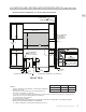


Table Of Contents
- SAFETY PRECAUTIONS - BEFORE YOU BEGIN
- MODEL NUMBERS
- RATING LABEL
- REGULATORY / CODE REQUIREMENTS
- LOCATION AND INSTALLATION / VENTILATION
- BACKGUARD AND ACCESSORIES
- INSTALLATION OF ANTI-TIP DEVICE
- ELECTRICAL CONNECTIONS
- GAS CONNECTION
- FINAL SETUP
- SERVICE
- APPENDIX
- PRÉCAUTIONS DE SÉCURITÉ - AVANT DE COMMENCER
- NUMÉROS DE MODÈLE
- PLAQUE SIGNALÉTIQUE
- RESPECT DE LA RÉGLEMENTATION ET DES CODES EN VIGUEUR
- EMPLACEMENT ET INSTALLATION / VENTILATION
- DOSSERET ET ACCESSOIRES
- INSTALLATION DU DISPOSITIF ANTI-BASCULEMENT
- BRANCHEMENTS ÉLECTRIQUES
- RACCORDEMENT DE GAZ
- PHASE FINALE DE L’INSTALLATION
- SERVICE
- APPENDICE

EN
©2020 Hestan Commercial Corporation
18
GAS SUPPLYGAS SUPPLY
The local gas authority or supplier should be consulted at the installation planning stage in order to
establish the availability of an adequate supply of gas (NG or LP). If it is a new installation, have the
gas authorities or supplier check the meter size and piping to assure that the unit is supplied with the
necessary amount of gas supply and pressure to operate the unit(s).
Gas connections should be made by a qualified plumber, or your professional appliance installer.
All appliances must be fitted with an accessible upstream gas shutoff valve as a means of isolating the
appliance for emergency shut off and for servicing.
Make certain new piping and connections have been made in a clean manner and have been purged
so that piping compound, chips, etc. will not clog regulators, valves, orifices, or burners. Use pipe
joint compound / thread sealant approved for natural and LP gases.
The appliance and its individual manual shutoff valve must be disconnected from the gas supply
piping system during any pressure testing of that system at test pressures in excess of 1/2 psi [3.5
kPa].
The appliance must be isolated from the gas supply piping system by closing its individual manual
shutoff valve during any pressure testing of that system at test pressures equal to or less than 1/2 psi
[3.5 kPa].
NEVER CONNECT THE APPLIANCE TO AN UNREGULATED GAS SUPPLY. Before proceeding,
ensure the appliance is fitted for Natural or Liquid Propane gas. Connecting to an improper gas type
will result in poor performance and increased risk of damage or injury. Gas type and gas consumption
(BTU per hour) for each burner type is shown on the rating label.
Installation of this cooking appliance must be made in accordance with local codes. In the absence of
local codes, this unit should be installed in accordance with the National Fuel Gas Code No.
Z223.1/
NFPA 54
, Natural Gas and Propane Installation code
CSA B149-1
, or Propane Storage and Handling
Code B149.2.
NOTE:NOTE: See rating label for manifold pressure for the type of gas of your appliance.
REGULATOR LOCATION REGULATOR LOCATION
Some range units may have the regulator mounted
internally as seen in Figure A. There is a short flex
hose which ends at a small bracket at the rear of the
range. This short flex hose has a connection end
with 1/2”NPT internal thread AND 3/4”NPT external
threads. The installer must connect a gas supply
hose at this location.
Other units have the regulator located externally
with a short flex hose and mounted to the rear of
the range with a bracket as shown in Figure B. The
regulator is shipped loose in the accessory box with
other items. The regulator must be connected to the
provided short flex hose by the installer, and then
the gas supply hose to the inlet side of the regulator.
Make a note of the flow arrow embossed on the
regulator itself. The arrow points toward the range.
The gas inlet of the regulator is 1/2”NPT thread.
Connect to the gas supply using a mininum 3/4” inside diameter (1” OD) flexible (semi-rigid) stainless
steel gas hose (not included) with appropriate fittings to prevent gas starvation. This hose should be
no more that 48” [1.2m] in length. Use the appropriate thread sealant on all connections, except flare
fittings.
The gas hose must not interfere with the rear of the range. Use caution when pushing the range
against the back wall, so that you do not kink or crimp the hose as this could result in a gas leak.
1/2”NPT
INTERNAL THREAD
FIGURE A: INTERNAL REGULATOR
3/4”NPT
EXTERNAL THREAD
GAS CONNECTION