
Installation Manual


EN
©2018 Hestan Commercial Corporation
6
LOCATION AND INSTALLATION/VENTILATION
(CONTINUED)
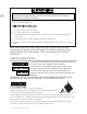
18” [45.7]
MIN.
W
3”
7.6
5”
12.7
24”
61
V
12”
30.5
19”
48.3
2-1/2”
6.4
6”
15.2
5”
12.7
9-1/2”
24.1
RECOMMENDED
GAS SHUT-OFF
VALVE LOCATION
ELECTRICAL
SUPPLY
LOCATION
G
FINISHED
FLOOR
VENT HOOD
MIN. CLEARANCE
TO NEAREST
COMBUSTIBLE
SIDE SURFACE
E
38-3/8 - 36-3/4”
[97.5 - 93.4]
TO COOKING
SURFACE
48-5/16”
122.7
3”
7.6
30-13/16”
78.3
24-11/16”
62.7
13” [33]
MAX.
LOCATION OF GAS
AND ELECTRICAL
ON FLOOR
LOW
BACKGUARD
MAX.
RECESS
DEPTH
APPLIANCE TOP
COOKING
SURFACE
COMBUSTIBLE
MATERIALS
COMBUSTIBLE
MATERIALS
INSTALLATION CLEARANCES WITH LOW BACKGUARD
FRONT VIEW
SIDE VIEW
NOTES:
* SHADED AREAS INDICATE WHERE COMBUSTIBLE MATERIALS ARE NOT ALLOWED.
* APPLIANCE TOP MUST BE LEVEL OR HIGHER THAN THE ADJACENT COUNTERTOP SURFACES.
* "G" IS GAS CONNECTION ZONE ON REAR WALL. MOUNT SHUT-OFF VALVE AS HIGH AS
POSSIBLE IN THIS ZONE FOR EASY ACCESS WHEN RANGE IS INSTALLED.
* "E" IS ELECTRICAL SUPPLY ZONE.
* "W" IS APPLIANCE OPENING.
* "V" IS MIN. CLEARANCE TO REQUIRED VENTILATION HOOD.
DIMENSIONS IN BRACKETS [ ] ARE IN CM.
LEVELING
The range must be level, especially those models featuring a griddle. Raise or lower the range to the
desired height by adjusting the four leveling legs under the range. The legs can be turned by hand. It
may be necessary to use a lever or other lifting device to assist in temporarily raising the unit to turn
the legs. Do not lift or lever from the front or back, only from the sides.
The appliance top
must be level or higher
than the adjacent
countertop surfaces. Failure to adjust the height
may expose the adjacent cabinets to excessive heat
which may damage the cabinets or countertop.
CAUTION